
ESP32-Based Smart Weather Station with DHT11 Sensor and TFT Display
View and Edit Project In Cirkit Designer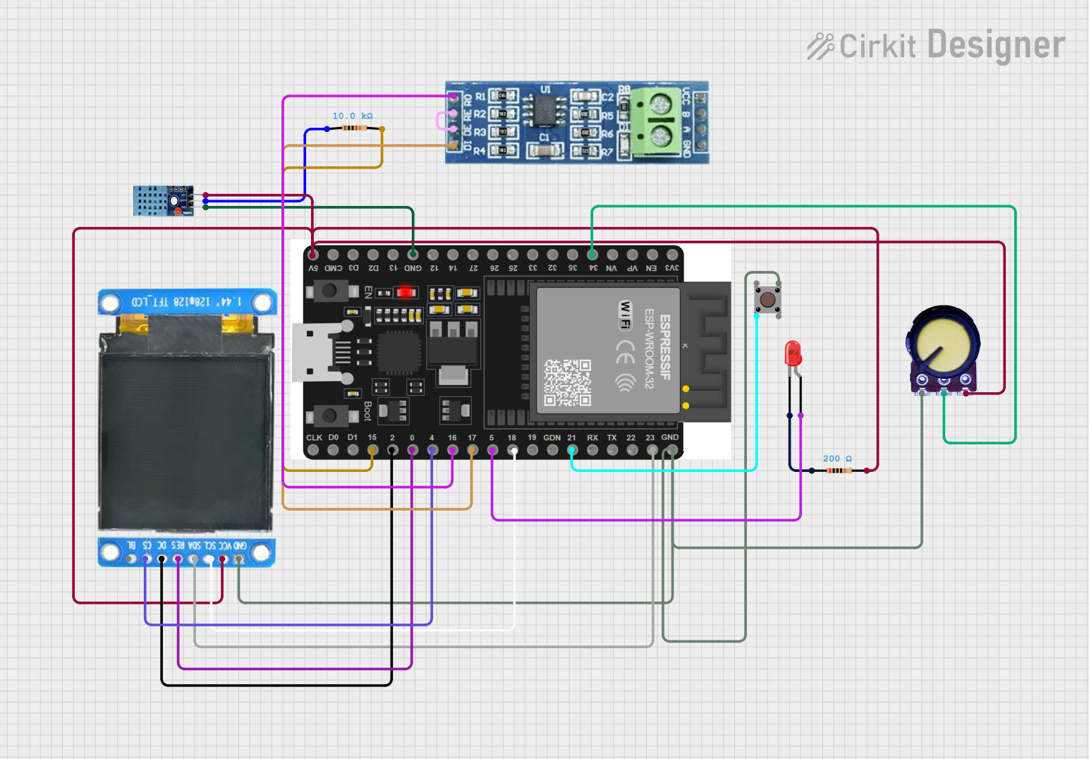
Circuit Documentation
Summary
This circuit is designed to read temperature and humidity from a DHT11 sensor, read the value from a potentiometer, and control an external LED based on the state of a pushbutton. The circuit uses an ESP32 microcontroller to interface with the sensors and the LED. Additionally, an ST7735 TFT display is used to show the readings, and an RS485 module is included for communication purposes.
Component List
ESP32 38 PINS
- Description: Microcontroller with Wi-Fi and Bluetooth capabilities.
- Pins: GND, 23, 22/SCL, 1, 2, 21/SDA, 19, 18, 5, 17/TX2, 16/RX2, 4, 0, 15, D1, D0, CLK, 3V3, EN, VP, VN, 34, 35, 32, 33, 25, 26, 27, 14, 12, 13, D2, D3, 11, 5V/VIN
DHT 11
- Description: Temperature and humidity sensor.
- Pins: VCC, GND, DATA
Resistor (10k Ohms)
- Description: Resistor with a resistance of 10k Ohms.
- Pins: pin1, pin2
Pushbutton
- Description: Pushbutton switch.
- Pins: Pin 3 (out), Pin 4 (out), Pin 1 (in), Pin 2 (in)
LED: Two Pin (red)
- Description: Red LED.
- Pins: cathode, anode
Resistor (200 Ohms)
- Description: Resistor with a resistance of 200 Ohms.
- Pins: pin1, pin2
Potentiometer
- Description: Variable resistor.
- Pins: GND, Output, VCC
ST7735 128x128 1.44 TFT I2C Color
- Description: TFT display.
- Pins: BL, C5, DC, RES, SDA, SCL, GND, VCC
RS485
- Description: RS485 communication module.
- Pins: VCC, RO, RE, GND, B, A, DE, DI
Wiring Details
ESP32 38 PINS
- GND: Connected to GND of ST7735, Pushbutton, Potentiometer, and DHT11.
- 23: Connected to SDA of ST7735.
- 21/SDA: Connected to Pin 2 (in) of Pushbutton.
- 18: Connected to SCL of ST7735.
- 5: Connected to anode of LED.
- 17/TX2: Connected to DI of RS485.
- 16/RX2: Connected to RO of RS485.
- 4: Connected to C5 of ST7735.
- 0: Connected to RES of ST7735.
- 2: Connected to DC of ST7735.
- 15: Connected to pin2 of 10k Ohm Resistor.
- 34: Connected to Output of Potentiometer.
- 5V/VIN: Connected to VCC of DHT11, ST7735, and Potentiometer.
DHT 11
- VCC: Connected to 5V/VIN of ESP32.
- GND: Connected to GND of ESP32.
- DATA: Connected to pin1 of 10k Ohm Resistor.
Resistor (10k Ohms)
- pin1: Connected to DATA of DHT11.
- pin2: Connected to 15 of ESP32.
Pushbutton
- Pin 3 (out): Connected to GND of ESP32.
- Pin 2 (in): Connected to 21/SDA of ESP32.
LED: Two Pin (red)
- anode: Connected to 5 of ESP32.
- cathode: Connected to pin1 of 200 Ohm Resistor.
Resistor (200 Ohms)
- pin1: Connected to cathode of LED.
- pin2: Connected to 5V/VIN of ESP32.
Potentiometer
- GND: Connected to GND of ESP32.
- Output: Connected to 34 of ESP32.
- VCC: Connected to 5V/VIN of ESP32.
ST7735 128x128 1.44 TFT I2C Color
- GND: Connected to GND of ESP32.
- SDA: Connected to 23 of ESP32.
- SCL: Connected to 18 of ESP32.
- C5: Connected to 4 of ESP32.
- RES: Connected to 0 of ESP32.
- DC: Connected to 2 of ESP32.
- VCC: Connected to 5V/VIN of ESP32.
RS485
- DI: Connected to 17/TX2 of ESP32.
- RO: Connected to 16/RX2 of ESP32.
- RE: Connected to DE of RS485.
- DE: Connected to RE of RS485.
Code Documentation
// This Arduino sketch reads temperature and humidity from a DHT11 sensor,
// reads the value from a potentiometer, and turns on an external LED when
// a button is pressed. The DHT11 sensor is connected to pin 4, the button
// is connected to pin 17/TX2 with a 10K pull-down resistor, the external
// LED is connected to pin 5, and the potentiometer is connected to pin 34.

#include "DHT.h" // Adafruit DHT library

#define DHTPIN 4     // Digital pin connected to the DHT sensor
#define DHTTYPE DHT11   // DHT 11
#define BUTTON_PIN 17   // Digital pin connected to the button
#define LED_PIN 5       // External LED pin
#define POT_PIN 34      // Analog pin connected to the potentiometer

DHT dht(DHTPIN, DHTTYPE);

void setup() {
  Serial.begin(9600);
  Serial.println(F("DHTxx test!"));

  dht.begin();
  pinMode(BUTTON_PIN, INPUT);
  pinMode(LED_PIN, OUTPUT);
}

void loop() {
  // Wait a few seconds between measurements.
  delay(500);

  // Reading temperature or humidity takes about 250 milliseconds!
  // Sensor readings may also be up to 2 seconds 'old' (its a very slow sensor)
  float h = dht.readHumidity();
  float t = dht.readTemperature();
  float f = dht.readTemperature(true);

  // Check if any reads failed and exit early (to try again).
  if (isnan(h) || isnan(t) || isnan(f)) {
    Serial.println(F("Failed to read from DHT sensor!"));
    return;
  }

  // Compute heat index in Fahrenheit (the default)
  float hif = dht.computeHeatIndex(f, h);
  // Compute heat index in Celsius (isFahreheit = false)
  float hic = dht.computeHeatIndex(t, h, false);

  Serial.print(F("Humidity: "));
  Serial.print(h);
  Serial.print(F("%  Temperature: "));
  Serial.print(t);
  Serial.print(F("°C "));
  Serial.print(f);
  Serial.print(F("°F  Heat index: "));
  Serial.print(hic);
  Serial.print(F("°C "));
  Serial.print(hif);
  Serial.println(F("°F"));

  // Read the potentiometer value
  int potValue = analogRead(POT_PIN);
  Serial.print(F("Potentiometer value: "));
  Serial.println(potValue);

  // Check if the button is pressed
  if (digitalRead(BUTTON_PIN) == HIGH) {
    digitalWrite(LED_PIN, HIGH); // Turn on the external LED
  } else {
    digitalWrite(LED_PIN, LOW); // Turn off the external LED
  }
}
This code initializes the DHT11 sensor, sets up the button and LED pins, and reads the temperature, humidity, and potentiometer values in the loop. It also controls the LED based on the button state.