
Arduino-Controlled Temperature Regulation System with Dual Relay Fans and Heating Elements
View and Edit Project In Cirkit Designer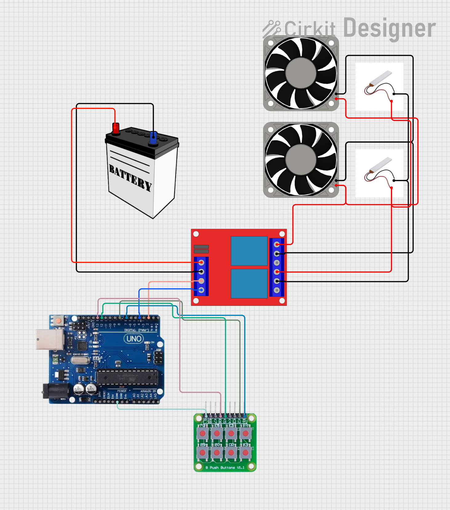
Circuit Documentation
Summary
The circuit in question is designed to control a heating element and two 12V fans using an Arduino Uno R3 microcontroller and a 2-channel 12V relay. The Arduino Uno R3 is programmed to respond to inputs from an 8-push button board PCB to toggle the state of the heating element and the fans. The circuit is powered by a 12V battery, which supplies power to the relay, fans, and indirectly to the heating element through the relay contacts.
Component List
12V Battery
- Description: A 12V power source used to supply power to the circuit.
- Pins: VCC, GND
40 Fan 12v (x2)
- Description: 12V fans used for cooling.
- Pins: +12V, -12V
Heating Element (x2)
- Description: Elements used for heating.
- Pins: (No explicit pins, likely connected internally)
Arduino Uno R3
- Description: Microcontroller board based on the ATmega328P used for controlling the circuit logic.
- Pins: USB Port, Power Jack, Not Connected, IOREF, RESET, 3.3V, 5V, GND, VIN, A0-A5, SCL, SDA, AREF, Digital Pins 0-13
2 Channel 12v Relay
- Description: Relay module used to control high power devices with Arduino's low power signals.
- Pins: 12v +, 12v -, Trigger 1, Trigger 2, NC1, COM1, NO1, NC2, COM2, NO2
8 Push Button Board PCB
- Description: A board with 8 push buttons used to provide input signals to the Arduino.
- Pins: K1-K8, GROUND
Wiring Details
12V Battery
- VCC connected to the 12v + of the 2 Channel 12v Relay.
- GND connected to the 12v - of the 2 Channel 12v Relay.
40 Fan 12v
- +12V of both fans connected to NC1 of the 2 Channel 12v Relay.
- -12V of both fans connected to COM1 of the 2 Channel 12v Relay.
Heating Element
- Both heating elements connected to COM2 and NC2 of the 2 Channel 12v Relay.
Arduino Uno R3
- GND connected to GROUND of the 8 Push Button Board PCB.
- Digital Pin 13 connected to K6 of the 8 Push Button Board PCB (Cooler Off).
- Digital Pin 12 connected to K5 of the 8 Push Button Board PCB (Cooler On).
- Digital Pin 8 connected to K2 of the 8 Push Button Board PCB (Heater Off).
- Digital Pin 7 connected to K1 of the 8 Push Button Board PCB (Heater On).
- Digital Pin 4 connected to Trigger 2 of the 2 Channel 12v Relay (Heater Control).
- Digital Pin 2 connected to Trigger 1 of the 2 Channel 12v Relay (Cooler Control).
2 Channel 12v Relay
- 12v + and 12v - connected to the 12V Battery.
- Trigger 1 and Trigger 2 controlled by Arduino Uno R3.
- NC1, COM1 connected to the 40 Fan 12v.
- NC2, COM2 connected to the Heating Element.
8 Push Button Board PCB
- K1-K8 connected to various digital pins on the Arduino Uno R3 for input.
- GROUND connected to GND on the Arduino Uno R3.
Documented Code
// Constants for readability
const bool off = HIGH;
const bool on = LOW;

// Pin assignments
int heater = 4;
int cooler = 2;
int heateron = 7;
int heateroff = 8;
int cooleron = 12;
int cooleroff = 13;

void setup() {
  // Initialize pins
  pinMode(cooler, OUTPUT);
  pinMode(heater, OUTPUT);
  pinMode(heateron, INPUT_PULLUP);
  pinMode(heateroff, INPUT_PULLUP);
  pinMode(cooleron, INPUT_PULLUP);
  pinMode(cooleroff, INPUT_PULLUP);

  // Start serial communication
  Serial.begin(9600);
}

void loop() {
  // Read the state of the push buttons
  if(digitalRead(heateron) == LOW) {
    digitalWrite(heater, on);
    Serial.print("Heater On");
  }
  if(digitalRead(heateroff) == LOW) {
    digitalWrite(heater, off);
    Serial.print("Heater Off");
  }
  if(digitalRead(cooleron) == LOW) {
    digitalWrite(cooler, on);
    Serial.print("Cooler On");
  }
  if(digitalRead(cooleroff) == LOW) {
    digitalWrite(cooler, off);
    Serial.print("Cooler Off");
  }
}
This code is designed to control the heating element and the fans based on the input from the push buttons. When a button is pressed, the corresponding device is either turned on or off, and a message is printed to the serial monitor. The INPUT_PULLUP mode is used for the buttons, which means they are expected to be connected to ground, and the internal pull-up resistors are enabled.