
ESP8266 NodeMCU with LoRa and RS-485 Communication and Ethernet Connectivity
View and Edit Project In Cirkit Designer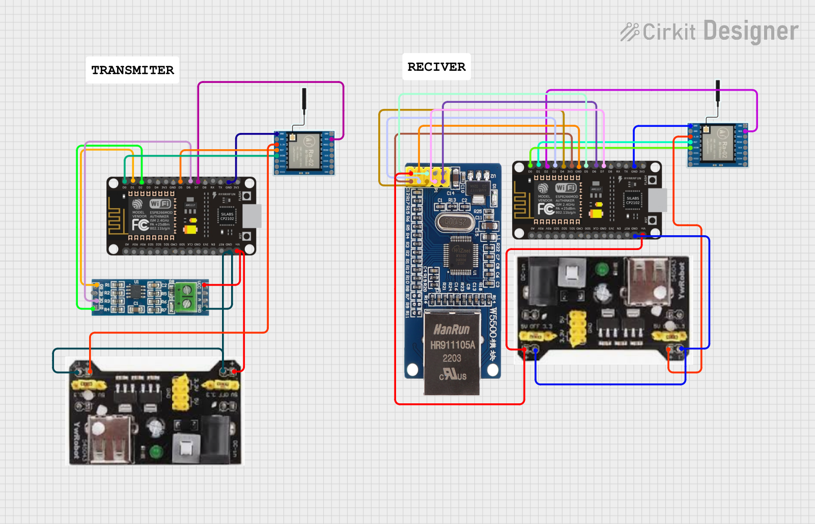
Circuit Documentation
Summary
This circuit integrates various communication modules with an ESP8266 NodeMCU microcontroller. It features two LoRa Ra-02 SX1278 modules for long-range communication, an RS-485 module for robust serial communication, and a W5500 Ethernet module for network connectivity. The circuit is powered by MB102 Breadboard Power Supply Modules that provide both 3.3V and 5V outputs. The ESP8266 NodeMCU serves as the central processing unit, interfacing with each module to facilitate different communication protocols.
Component List
ESP8266 NodeMCU
- Description: A WiFi-capable microcontroller module based on the ESP8266 chip.
- Pins: D0, D1, D2, D3, D4, 3V3, GND, D5, D6, D7, D8, RX, TX, A0, RSV, SD3, SD2, SD1, CMD, SD0, CLK, EN, RST, VIN
LoRa Ra-02 SX1278
- Description: A long-range wireless communication module based on the SX1278 chip.
- Pins: GND, NSS, MOSI, MISO, SCK, D105, DI04, 3.3V, RST, DI00, DI01, D102, DI03
RS-485 Module
- Description: A module for RS-485 serial communication.
- Pins: VCC, B, A, GND, RO, RE, DE, DI
Module Ethernet W5500
- Description: A network module based on the W5500 chip for Ethernet connectivity.
- Pins: NC, INT, RST, GND, 5V, SCK, SS, MOSI, MISO, 3.3V
MB102 Breadboard Power Supply Module 3.3V/5V
- Description: A power supply module that provides 3.3V and 5V outputs for breadboard projects.
- Pins: GND, 3.3V, 5V
Comment
- Description: A placeholder for comments or notes within the circuit design.
Wiring Details
ESP8266 NodeMCU
- D7: Connected to LoRa Ra-02 SX1278 NSS
- GND: Common ground with all modules
- D5: Connected to LoRa Ra-02 SX1278 RST
- D0: Connected to LoRa Ra-02 SX1278 DI00
- VIN: Connected to RS-485 Module VCC and MB102 Power Supply 5V
- D1: Connected to RS-485 Module RO and LoRa Ra-02 SX1278 RST
- D6: Connected to RS-485 Module DE and Module Ethernet W5500 SCK
- D2: Connected to RS-485 Module DI and LoRa Ra-02 SX1278 NSS
- 3V3: Connected to Module Ethernet W5500 3.3V
LoRa Ra-02 SX1278
- NSS: Connected to ESP8266 NodeMCU D7 or D2
- GND: Common ground with all modules
- 3.3V: Connected to MB102 Power Supply 3.3V
- RST: Connected to ESP8266 NodeMCU D5 or D1
- DI00: Connected to ESP8266 NodeMCU D0
RS-485 Module
- VCC: Connected to ESP8266 NodeMCU VIN and MB102 Power Supply 5V
- GND: Common ground with all modules
- RO: Connected to ESP8266 NodeMCU D1
- RE: Not connected
- DE: Connected to ESP8266 NodeMCU D6
- DI: Connected to ESP8266 NodeMCU D2
Module Ethernet W5500
- RST: Connected to ESP8266 NodeMCU D5
- GND: Common ground with all modules
- 5V: Connected to ESP8266 NodeMCU VIN and MB102 Power Supply 5V
- SCK: Connected to ESP8266 NodeMCU D6
- SS: Connected to ESP8266 NodeMCU D7
- MOSI: Connected to ESP8266 NodeMCU D4
- MISO: Connected to ESP8266 NodeMCU D3
- 3.3V: Connected to ESP8266 NodeMCU 3V3
MB102 Breadboard Power Supply Module 3.3V/5V
- GND: Common ground with all modules
- 3.3V: Connected to LoRa Ra-02 SX1278 3.3V
- 5V: Connected to ESP8266 NodeMCU VIN and RS-485 Module VCC
Documented Code
No code has been provided for the microcontrollers in the circuit. The documentation of the code would typically include descriptions of the functionality implemented, setup and loop functions for Arduino-based microcontrollers, and any libraries or external dependencies required for the code to run. It would also include comments within the code to explain the purpose of each section and how it interacts with the connected hardware components.