
Circuit Documentation
Summary
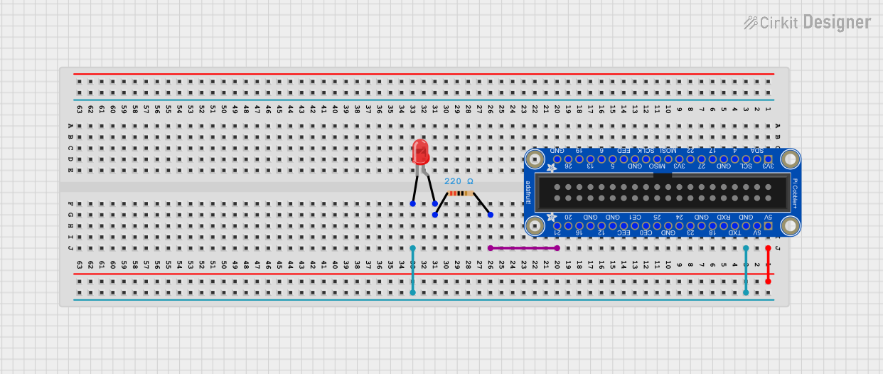
This document provides a detailed description of a simple circuit involving an Adafruit Pi Cobbler Plus, a red LED, and a resistor. The circuit is designed to control the LED using a GPIO pin from the Pi Cobbler Plus.
Component List
Adafruit Pi Cobbler Plus
- Description: A breakout board for the Raspberry Pi GPIO pins.
- Pins: +3.3V, SDA, SCL, GPIO4, GND, GPIO17, GPIO27, GPIO22, MOSI, MISO, SCLK, EEDAT, GPIO5, GPIO6, GPIO13, GPIO19, GPIO26, +5V, TXD, RXD, GPIO18, GPIO23, GPIO24, GPIO25, CE0, CE1, EECLK, GPIO12, GPIO16, GPIO20, GPIO21
LED: Two Pin (red)
- Description: A standard red LED with two pins.
- Pins: cathode, anode
Resistor
- Description: A resistor with a resistance of 220 Ohms.
- Pins: pin1, pin2
- Properties:
- Resistance: 220 Ohms
Wiring Details
Adafruit Pi Cobbler Plus
- Pin +5V: Not connected
- Pin GND: Connected to LED cathode
- Pin GPIO21: Connected to Resistor pin2
LED: Two Pin (red)
- Pin cathode: Connected to Adafruit Pi Cobbler Plus GND
- Pin anode: Connected to Resistor pin1
Resistor
- Pin pin1: Connected to LED anode
- Pin pin2: Connected to Adafruit Pi Cobbler Plus GPIO21
Code
There is no code provided for this circuit.
This documentation provides a comprehensive overview of the circuit, including the components used, their connections, and the absence of any embedded code.