Cirkit Designer
Your all-in-one circuit design IDE
Home /
Project Documentation
Arduino Nano Based GPS Tracker with GSM Module for Emergency Alerts
Circuit Documentation
Summary
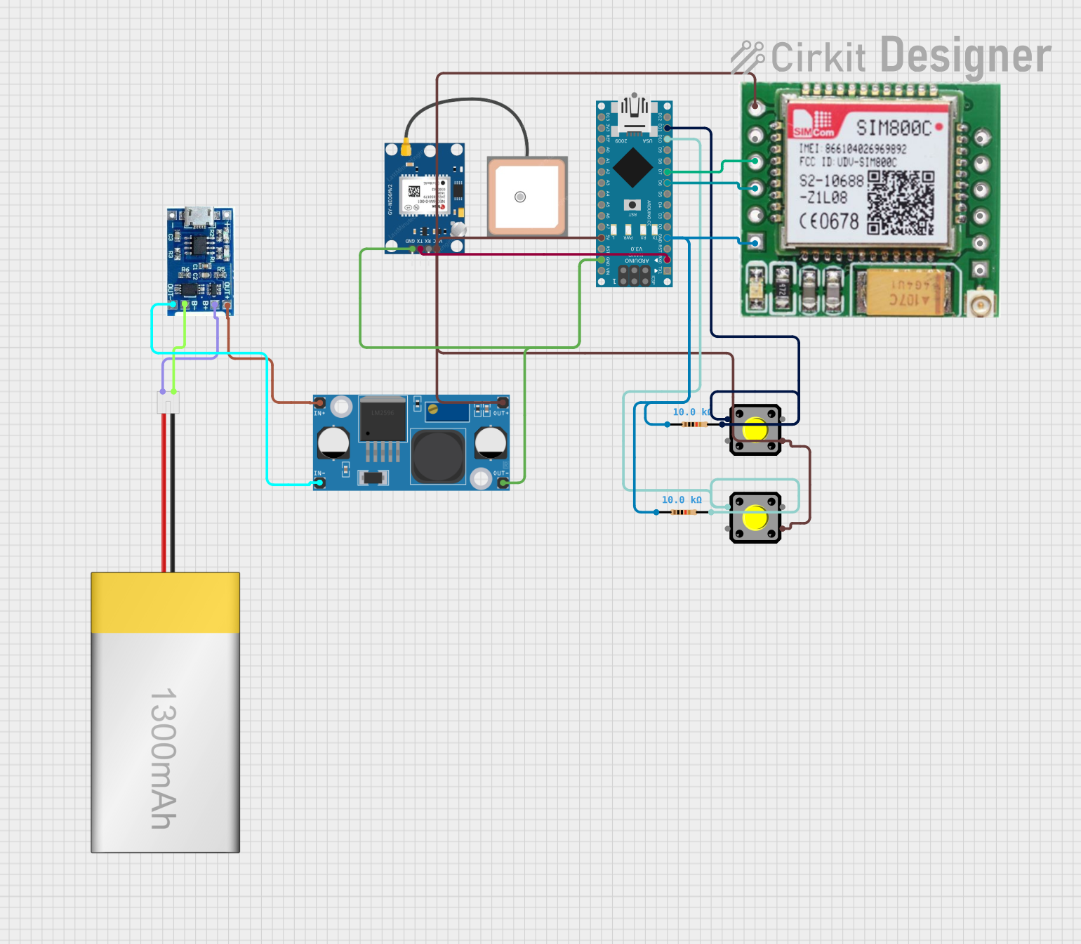
This circuit is designed to interface a GPS module and a GSM module with an Arduino Nano microcontroller. It includes functionality for receiving GPS data, sending SMS messages, and making calls. The circuit also features two pushbuttons with pull-up resistors and a power supply section that includes a LiPoly battery, a charger module, and a buck converter to regulate the voltage.
Component List
Arduino Nano
- Microcontroller board based on the ATmega328P
- Features digital and analog I/O pins
- Provides serial communication via UART
GPS NEO 6M
- GPS module for satellite positioning
- Communicates with the Arduino Nano via serial interface
SIM800c GSM Module
- GSM module for cellular communication
- Capable of sending SMS and making voice calls
- Interfaces with the Arduino Nano for control signals
Pushbutton (x2)
- Momentary tactile switch
- Used to trigger actions in the circuit
Resistor (x2)
- 10,000 Ohm resistors
- Serve as pull-up resistors for the pushbuttons
LM2956 Buck Converter DC-DC
- Voltage regulator to step down voltage
- Provides a stable power supply for the circuit components
LiPoly Battery (1300mAh)
- Rechargeable lithium polymer battery
- Supplies power to the circuit
LiPo Battery Charger Module
- Charges the LiPoly battery
- Provides power output for the circuit
Wiring Details
Arduino Nano
D0/RXconnected toTXof GPS NEO 6MD6connected toMIC+of SIM800c GSM ModuleD7connected toMIC-of SIM800c GSM ModuleD10connected to one pushbutton and a 10k resistorD11/MOSIconnected to another pushbutton and a 10k resistorGNDconnected to the common ground net5Vconnected to the power supply net
GPS NEO 6M
TXconnected toD0/RXof Arduino NanoGNDconnected to the common ground netVCCconnected to the power supply net
SIM800c GSM Module
RINGconnected to a 10k resistor and the common ground netMIC+connected toD6of Arduino NanoMIC-connected toD7of Arduino NanoSPK-connected to the power supply net
Pushbutton (x2)
- One side connected to
D10orD11/MOSIof Arduino Nano - The other side connected to a 10k resistor
Resistor (x2)
- One side connected to a pushbutton
- The other side connected to the common ground net
LM2956 Buck Converter DC-DC
OUT-connected to the common ground netOUT+connected to the power supply netIN+connected toOUT+of LiPo Battery Charger ModuleIN-connected toOUT-of LiPo Battery Charger Module
LiPoly Battery (1300mAh)
positiveconnected toB+of LiPo Battery Charger Modulenegativeconnected toB-of LiPo Battery Charger Module
LiPo Battery Charger Module
B+connected topositiveof LiPoly BatteryB-connected tonegativeof LiPoly BatteryOUT+connected toIN+of LM2956 Buck ConverterOUT-connected toIN-of LM2956 Buck Converter
Documented Code
#include <TinyGPS++.h>
#include <SoftwareSerial.h>

TinyGPSPlus gps;          // Use TinyGPSPlus class
SoftwareSerial Gsm(6, 7); // GSM module connected to pins 6 (RX) and 7 (TX)
char phone_no[] = "+91xxxxxxxxxx"; // Replace with actual phone number

int buttonPin = 10; // Button pin
int state;
String textMessage;

void setup() {
  Serial.begin(9600);  // For GPS module
  Gsm.begin(9600);     // For SIM800L GSM module

  // Set GSM to text mode and configure SMS reception
  Gsm.print("AT+CMGF=1\r");
  delay(100);
  Gsm.print("AT+CNMI=2,2,0,0,0\r");
  delay(100);

  pinMode(buttonPin, INPUT); // Button input
  enterIdleMode();  // Start in idle mode
}

void loop() {
  state = digitalRead(buttonPin);  // Check if button is pressed

  if (state == LOW) {  // If button is pressed
    wakeUp();  // Exit idle mode
    sendEmergencyAlert();  // Send alert and call
    enterIdleMode();  // Return to idle mode after task completion
  }

  if (Gsm.available() > 0) {  // If an SMS is received
    textMessage = Gsm.readString();
    textMessage.toUpperCase();  // Convert text to uppercase for case-insensitive comparison

    if (textMessage.indexOf("SEND LOCATION") >= 0) {  // If "SEND LOCATION" command is received
      wakeUp();  // Exit idle mode
      sendLocation();  // Send current location
      enterIdleMode();  // Return to idle mode
    }
  }
}

void sendEmergencyAlert() {
  if (getGPSData()) {  // If GPS data is valid
    Gsm.print("AT+CMGF=1\r");
    delay(400);
    Gsm.print("AT+CMGS=\"");
    Gsm.print(phone_no);
    Gsm.println("\"");
    Gsm.println("Alert! I need help.");
    Gsm.print("http://maps.google.com/maps?q=loc:");
    Gsm.print(gps.location.lat(), 6);  // Latitude
    Gsm.print(",");
    Gsm.print(gps.location.lng(), 6);  // Longitude
    delay(200);
    Gsm.println((char)26);  // End of SMS
    delay(200);
    Serial.println("Emergency SMS Sent");

    // Make an emergency call
    Serial.println("Calling...");
    Gsm.println("ATD+91xxxxxxxxxx;");  // Replace with actual phone number
    delay(20000);  // 20 seconds call duration
    Gsm.println("ATH");  // Hang up the call
    delay(1000);
  } else {
    Serial.println("Failed to get GPS data.");
  }
}

void sendLocation() {
  if (getGPSData()) {  // If GPS data is valid
    Gsm.print("AT+CMGF=1\r");
    delay(400);
    Gsm.print("AT+CMGS=\"");
    Gsm.print(phone_no);
    Gsm.println("\"");
    Gsm.println("Here is my current location:");
    Gsm.print("http://maps.google.com/maps?q=loc:");
    Gsm.print(gps.location.lat(), 6);  // Latitude
    Gsm.print(",");
    Gsm.print(gps.location.lng(), 6);  // Longitude
    delay(200);
    Gsm.println((char)26);  // End of SMS
    delay(200);
    Serial.println("Location SMS Sent");
  } else {
    Serial.println("Failed to get GPS data.");
  }
}

bool getGPSData() {
  bool newData = false;
  unsigned long start = millis();

  while (millis() - start < 10000) {  // Retry for 10 seconds
    while (Serial.available()) {
      char c = Serial.read();
      gps.encode(c);  // Process GPS data

      if (gps.location.isUpdated()) {
        newData = true;  // New GPS data received
      }
    }
  }

  if (!newData) {
    Serial.println("GPS fix failed.");
  }

  return newData;
}

void enterIdleMode() {
  // Code to reduce power consumption (e.g., disabling unused peripherals)
  Serial.println("Entering idle mode...");
  delay(100);
}

void wakeUp() {
  // Code to re-enable peripherals and prepare for operation
  Serial.println("Waking up from idle mode...");
  delay(100);
}
This code is designed to run on the Arduino Nano and provides the logic for the circuit's operation. It includes functions for sending emergency alerts, sending the current location, and managing power consumption modes. The code uses the TinyGPS++ library to parse GPS data and the SoftwareSerial library to communicate with the GSM module.