
Arduino and ESP8266 Controlled Environmental Monitoring and Waste Management System
View and Edit Project In Cirkit Designer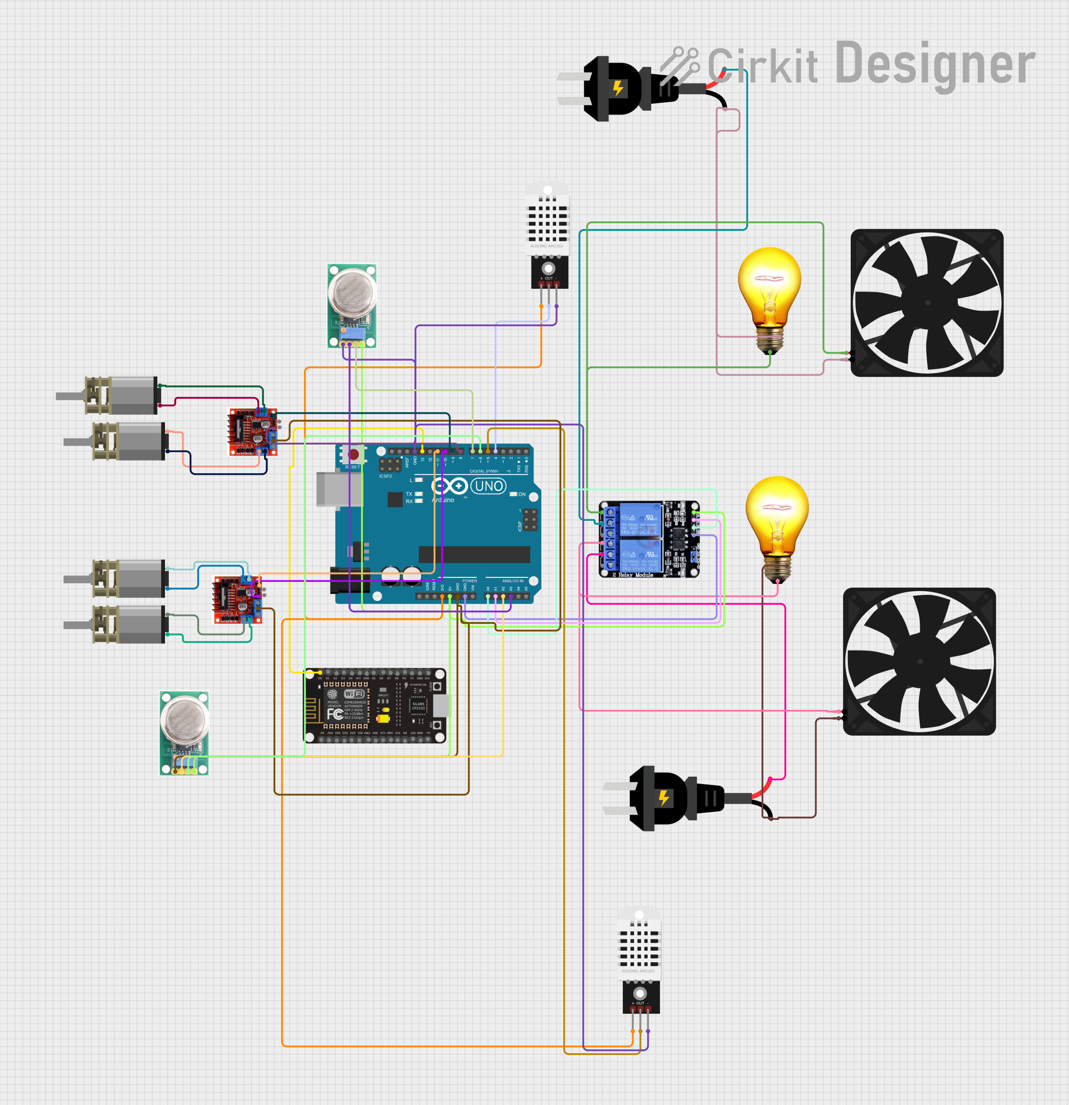
Circuit Documentation
Summary
The circuit is designed to monitor environmental conditions and control devices within a chicken coop and waste disposal system. It features temperature and gas detection sensors, motor drivers for actuator control, and relays for managing AC-powered devices such as a fan and light bulb. The core of the system is an Arduino UNO microcontroller, which processes sensor data and controls the connected devices based on predefined conditions.
Component List
DHT22 (Temperature and Humidity Sensor)
- Description: A sensor for measuring temperature and humidity.
- Pins:
+(Power),Out(Signal Output),-(Ground).
Arduino UNO (Microcontroller Board)
- Description: A microcontroller board based on the ATmega328P.
- Pins: Various digital and analog I/O pins, power, and ground.
ESP8266 NodeMCU (Wi-Fi Microcontroller)
- Description: A Wi-Fi enabled microcontroller for IoT applications.
- Pins: Digital I/O, analog input, power, and ground.
L298N Motor Driver (Motor Controller Module)
- Description: A dual H-bridge motor driver for controlling the direction and speed of motors.
- Pins: Motor outputs, control inputs, power, and ground.
DC Mini Metal Gear Motor
- Description: A small DC motor with a gearbox for increased torque.
- Pins:
IN1andIN2for motor control.
MQ-136 (Gas Sensor)
- Description: A sensor for detecting hydrogen sulfide gas concentrations.
- Pins:
GND(Ground),OUT1(Analog Output),OUT2(Digital Output),VCC(Power).
AC Bulb
- Description: A standard AC-powered light bulb.
- Pins:
P(Phase),N(Neutral).
Fan
- Description: An electric fan for air circulation.
- Pins:
GND(Ground),5V(Power).
Two Channel Relay 5V
- Description: A relay module for controlling high power AC devices.
- Pins:
VCC(Power),IN1andIN2(Control Inputs),GND(Ground),NC1,C1,NO1,NC2,C2,NO2(Relay Contacts).
AC Source
- Description: An alternating current power source.
- Pins:
+(Phase),-(Neutral).
Wiring Details
DHT22 Sensors
- Powered by the 3.3V output from the Arduino UNO.
- Signal outputs connected to digital pins D4 and D5 on the Arduino UNO.
- Ground connected to the GND pin on the Arduino UNO.
Arduino UNO
- Acts as the central controller for the circuit.
- Digital and analog pins are used to interface with sensors, relays, and motor drivers.
- Power pins provide voltage to other components.
ESP8266 NodeMCU
- Digital pin D0 is connected to digital pin D13 on the Arduino UNO for potential communication or control signals.
L298N Motor Drivers
- Motor control inputs connected to digital pins D8, D9, D10, and D11 on the Arduino UNO.
- Ground connected to the GND pin on the Arduino UNO.
DC Mini Metal Gear Motors
- Controlled by the L298N Motor Drivers.
- Each motor has two control inputs connected to the corresponding outputs on the L298N Motor Drivers.
MQ-136 Gas Sensors
- Analog outputs connected to analog pins A2 and A3 on the Arduino UNO.
- Digital outputs connected to digital pins D6 and D7 on the Arduino UNO.
- Powered by the 5V output from the Arduino UNO.
- Ground connected to the GND pin on the Arduino UNO.
AC Bulbs
- Connected to the normally closed (NC) contacts of the Two Channel Relay.
- Powered by the AC Source.
Fans
- Connected to the normally closed (NC) contacts of the Two Channel Relay.
- Powered by the AC Source.
Two Channel Relay 5V
- Control inputs connected to analog pins A0 and A1 on the Arduino UNO.
- Powered by the 5V output from the Arduino UNO.
- Ground connected to the GND pin on the Arduino UNO.
- Relay contacts connected to the AC Bulbs and Fans, and interfaced with the AC Source.
AC Sources
- Provide power to the AC Bulbs and Fans through the Two Channel Relay.
Documented Code
/*
 * Arduino Sketch for monitoring temperature and controlling devices
 * in a chicken coop and waste disposal system.
 *
 * Components:
 * - DHT22 sensors for temperature monitoring
 * - MQ-136 sensors for gas detection
 * - L298N Motor Driver for motor control
 * - Two Channel Relay for controlling AC devices
 * - Fan and AC Bulb for environmental control
 *
 * Connections:
 * - DHT22 sensors connected to D4 and D5
 * - MQ-136 sensors connected to A2, D6, A3, and D7
 * - L298N Motor Driver connected to D8, D9, D10, and D11
 * - Relay connected to A0 and A1
 * - Fan and AC Bulb connected to Relay
 */

#include <DHT.h>

#define DHTPIN1 4
#define DHTPIN2 5
#define DHTTYPE DHT22

DHT dht1(DHTPIN1, DHTTYPE);
DHT dht2(DHTPIN2, DHTTYPE);

#define MQ136_A2 A2
#define MQ136_D6 6
#define MQ136_A3 A3
#define MQ136_D7 7

#define RELAY_IN1 A0
#define RELAY_IN2 A1

#define MOTOR_IN1_1 8
#define MOTOR_IN4_1 9
#define MOTOR_IN1_2 10
#define MOTOR_IN4_2 11

void setup() {
  Serial.begin(9600);
  dht1.begin();
  dht2.begin();

  pinMode(MQ136_A2, INPUT);
  pinMode(MQ136_D6, INPUT);
  pinMode(MQ136_A3, INPUT);
  pinMode(MQ136_D7, INPUT);

  pinMode(RELAY_IN1, OUTPUT);
  pinMode(RELAY_IN2, OUTPUT);

  pinMode(MOTOR_IN1_1, OUTPUT);
  pinMode(MOTOR_IN4_1, OUTPUT);
  pinMode(MOTOR_IN1_2, OUTPUT);
  pinMode(MOTOR_IN4_2, OUTPUT);
}

void loop() {
  float temp1 = dht1.readTemperature();
  float temp2 = dht2.readTemperature();

  int gas1 = analogRead(MQ136_A2);
  int gas2 = digitalRead(MQ136_D6);
  int gas3 = analogRead(MQ136_A3);
  int gas4 = digitalRead(MQ136_D7);

  Serial.print("Temp1: ");
  Serial.print(temp1);
  Serial.print(" C, Temp2: ");
  Serial.print(temp2);
  Serial.println(" C");

  Serial.print("Gas1: ");
  Serial.print(gas1);
  Serial.print(", Gas2: ");
  Serial.print(gas2);
  Serial.print(", Gas3: ");
  Serial.print(gas3);
  Serial.print(", Gas4: ");
  Serial.println(gas4);

  if (temp1 > 30 || temp2 > 30) {
    digitalWrite(RELAY_IN1, HIGH);
    digitalWrite(RELAY_IN2, HIGH);
  } else {
    digitalWrite(RELAY_IN1, LOW);
    digitalWrite(RELAY_IN2, LOW);
  }

  if (gas1 > 300 || gas2 == HIGH || gas3 > 300 || gas4 == HIGH) {
    digitalWrite(MOTOR_IN1_1, HIGH);
    digitalWrite(MOTOR_IN4_1, HIGH);
    digitalWrite(MOTOR_IN1_2, HIGH);
    digitalWrite(MOTOR_IN4_2, HIGH);
  } else {
    digitalWrite(MOTOR_IN1_1, LOW);
    digitalWrite(MOTOR_IN4_1, LOW);
    digitalWrite(MOTOR_IN1_2, LOW);
    digitalWrite(MOTOR_IN4_2, LOW);
  }

  delay(2000);
}
This code is responsible for initializing the sensors and actuators, reading temperature and gas levels, and controlling the relay and motors based on the sensor readings. It uses the DHT library for interfacing with the DHT22 sensors. The relay is activated if the temperature exceeds 30 degrees Celsius, and the motors are activated if any of the gas sensors detect a level higher than 300 or a digital HIGH signal.