
ESP8266 NodeMCU-Based Smart Home Environment Monitor with Wi-Fi Connectivity
View and Edit Project In Cirkit Designer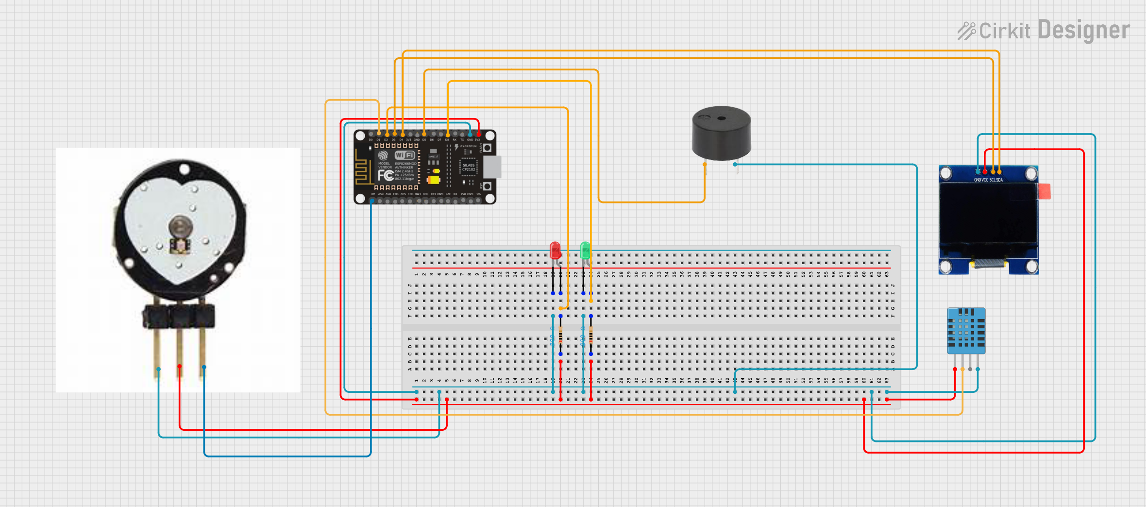
Circuit Documentation
Summary
This circuit is designed using an ESP8266 NodeMCU microcontroller to interface with various components including LEDs, a buzzer, a pulse sensor, an OLED display, and a DHT11 humidity and temperature sensor. The circuit is powered by the 3.3V and GND pins of the ESP8266. The microcontroller reads data from the sensors and controls the LEDs and buzzer based on the sensor inputs.
Component List
ESP8266 NodeMCU
- Description: A low-cost Wi-Fi microcontroller with GPIO, ADC, and other interfaces.
- Pins: D0, D1, D2, D3, D4, 3V3, GND, D5, D6, D7, D8, RX, TX, A0, RSV, SD3, SD2, SD1, CMD, SD0, CLK, EN, RST, VIN
LED: Two Pin (red)
- Description: A red LED with two pins: anode and cathode.
- Pins: cathode, anode
LED: Two Pin (green)
- Description: A green LED with two pins: anode and cathode.
- Pins: cathode, anode
Resistor (200 Ohms)
- Description: A resistor with a resistance of 200 Ohms.
- Pins: pin1, pin2
Buzzer
- Description: A simple buzzer with two pins: PIN and GND.
- Pins: PIN, GND
DHT11 Humidity and Temperature Sensor
- Description: A sensor for measuring humidity and temperature.
- Pins: VDD, DATA, NULL, GND
OLED 1.3" Display
- Description: A 1.3-inch OLED display with I2C interface.
- Pins: GND, VCC, SCL, SDA
Pulse Sensor
- Description: A sensor for measuring pulse rate.
- Pins: gnd, vcc, ao
Wiring Details
ESP8266 NodeMCU
- GND: Connected to the cathode of the red LED, cathode of the green LED, GND of the pulse sensor, GND of the buzzer, GND of the OLED display, and GND of the DHT11 sensor.
- 3V3: Connected to pin1 of the first resistor, pin1 of the second resistor, VCC of the pulse sensor, VCC of the OLED display, and VDD of the DHT11 sensor.
- D2: Connected to pin2 of the first resistor, which is connected to the anode of the red LED.
- D8: Connected to pin2 of the second resistor, which is connected to the anode of the green LED.
- D1: Connected to the DATA pin of the DHT11 sensor.
- D3: Connected to the SCL pin of the OLED display.
- D4: Connected to the SDA pin of the OLED display.
- D5: Connected to the PIN of the buzzer.
- A0: Connected to the ao pin of the pulse sensor.
LED: Two Pin (red)
- cathode: Connected to GND of the ESP8266.
- anode: Connected to pin2 of the first resistor.
LED: Two Pin (green)
- cathode: Connected to GND of the ESP8266.
- anode: Connected to pin2 of the second resistor.
Resistor (200 Ohms)
- First Resistor
- pin1: Connected to 3V3 of the ESP8266.
- pin2: Connected to the anode of the red LED and D2 of the ESP8266.
- Second Resistor
- pin1: Connected to 3V3 of the ESP8266.
- pin2: Connected to the anode of the green LED and D8 of the ESP8266.
Buzzer
- PIN: Connected to D5 of the ESP8266.
- GND: Connected to GND of the ESP8266.
DHT11 Humidity and Temperature Sensor
- VDD: Connected to 3V3 of the ESP8266.
- DATA: Connected to D1 of the ESP8266.
- GND: Connected to GND of the ESP8266.
OLED 1.3" Display
- GND: Connected to GND of the ESP8266.
- VCC: Connected to 3V3 of the ESP8266.
- SCL: Connected to D3 of the ESP8266.
- SDA: Connected to D4 of the ESP8266.
Pulse Sensor
- gnd: Connected to GND of the ESP8266.
- vcc: Connected to 3V3 of the ESP8266.
- ao: Connected to A0 of the ESP8266.
Code
No code provided for this circuit.