
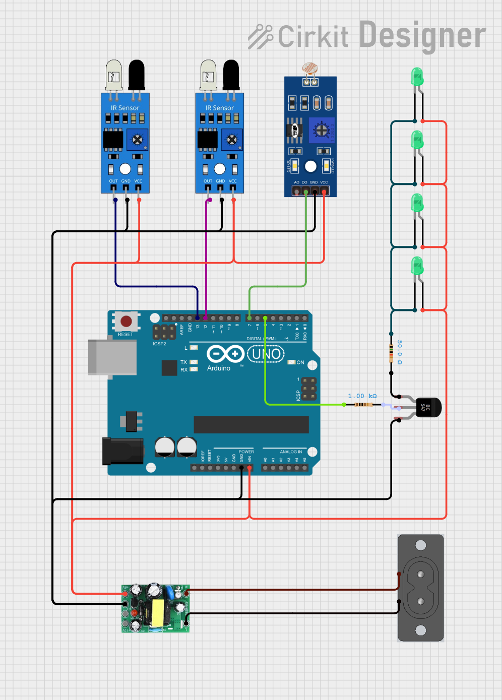
Circuit Documentation
Summary
This document provides a detailed overview of a circuit that includes an Arduino UNO microcontroller, IR sensors, a Light Dependent Resistor (LDR), a BC547 Transistor, LEDs, resistors, and an AC-DC Power Supply Unit (PSU) board. The circuit is designed to interface with IR sensors and an LDR to perform tasks based on light intensity and IR detection, with the Arduino UNO as the central processing unit. The PSU board converts AC power to DC for the circuit, and the LEDs serve as indicators.
Component List
Arduino UNO
- Microcontroller board based on the ATmega328P
- Digital I/O Pins: 14 (of which 6 provide PWM output)
- Analog Input Pins: 6
- Operating Voltage: 5V
IR Sensor
- Infrared sensor with digital output
- Operating Voltage: Typically 5V
Resistor (1k Ohm)
- Passive two-terminal electrical component
- Resistance: 1000 Ohms
Resistor (50 Ohm)
- Passive two-terminal electrical component
- Resistance: 50 Ohms
BC547 Transistor
- NPN Bipolar Junction Transistor (BJT)
- Used for amplification and switching
LDR (Light Dependent Resistor)
- Sensor that changes resistance with light intensity
- Used for detecting light levels
AC-DC PSU Board 220V-5V&12V
- Power supply unit that converts AC to 5V and 12V DC
- Input Voltage: 220V AC
2 Prong AC Socket
- Connector for AC power input
LED: Two Pin (Green)
- Light Emitting Diode
- Color: Green
- Used as an indicator light
Wiring Details
Arduino UNO
- D13: Connected to IR Sensor (Output)
- GND: Common ground with IR Sensors, LDR, BC547 Transistor, and AC-DC PSU Board
- Vin: Connected to +5V from AC-DC PSU Board
- D12: Connected to IR Sensor (Output)
- D7: Connected to LDR (D0)
- D5: Connected to Resistor (1k Ohm)
IR Sensor
- Out: Connected to Arduino UNO (D13, D12)
- GND: Common ground
- VCC: Connected to +5V from AC-DC PSU Board
Resistor (1k Ohm)
- Pin1: Connected to Arduino UNO (D5)
- Pin2: Connected to BC547 Transistor (Base)
Resistor (50 Ohm)
- Pin1: Connected to LED cathodes
- Pin2: Connected to BC547 Transistor (Collector)
BC547 Transistor
- Collector: Connected to Resistor (50 Ohm)
- Base: Connected to Resistor (1k Ohm)
- Emitter: Common ground
LDR
- GND: Common ground
- VCC: Connected to +5V from AC-DC PSU Board
- D0: Connected to Arduino UNO (D7)
AC-DC PSU Board 220V-5V&12V
- AC-N: Connected to 2 Prong AC Socket (AC -)
- AC-L: Connected to 2 Prong AC Socket (AC +)
- +5V: Connected to Arduino UNO (Vin), IR Sensors, LDR, and LED anodes
- GND: Common ground
2 Prong AC Socket
- AC +: Connected to AC-DC PSU Board (AC-L)
- AC -: Connected to AC-DC PSU Board (AC-N)
LED: Two Pin (Green)
- Cathode: Connected to common ground through Resistor (50 Ohm)
- Anode: Connected to +5V from AC-DC PSU Board
Documented Code
Arduino UNO Code (sketch.ino)
void setup() {
  // put your setup code here, to run once:

}

void loop() {
  // put your main code here, to run repeatedly:

}
Additional Notes
- The provided code for the Arduino UNO is a template with empty
setup()andloop()functions. The actual implementation should be added based on the desired functionality of the circuit. - The
documentation.txtfile is mentioned but contains no code or content. It is likely intended for additional notes or manual documentation.