
Smart Water Flow Monitoring System with Arduino UNO, ESP32, and PZEM004t
View and Edit Project In Cirkit Designer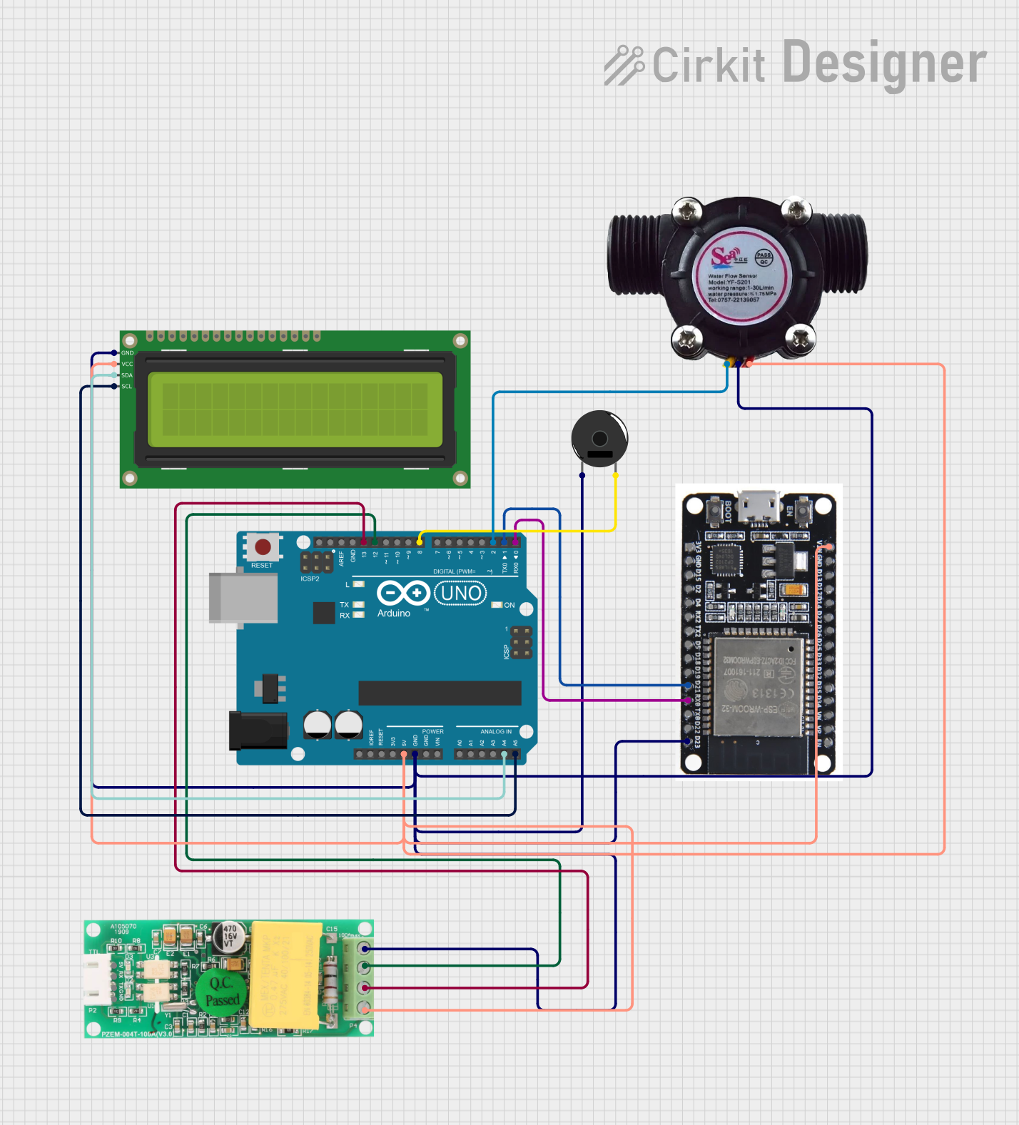
Circuit Documentation
Summary
This circuit is designed to monitor power usage, water flow, and display the data on an LCD. It consists of an Arduino UNO, an ESP32, a PZEM004t power monitoring module, a 16x2 I2C LCD, a water flow sensor, and a piezo buzzer. The ESP32 is used for WiFi connectivity and MQTT communication, while the Arduino UNO handles the main control logic and interfaces with the sensors and display.
Component List
PZEM004t
- Description: Power monitoring module
- Pins: VCC, RX, TX, GND, IN, OUT
Arduino UNO
- Description: Microcontroller board
- Pins: UNUSED, IOREF, Reset, 3.3V, 5V, GND, Vin, A0, A1, A2, A3, A4, A5, SCL, SDA, AREF, D13, D12, D11, D10, D9, D8, D7, D6, D5, D4, D3, D2, D1, D0
ESP32
- Description: WiFi and Bluetooth microcontroller
- Pins: EN, VP, VN, D34, D35, D32, D33, D25, D26, D27, D14, D12, D13, GND, VIN, 3V3, D15, D2, D4, RX2, TX2, D5, D18, D19, D21, RX0, TX0, D22, D23, BOOT
Piezo Buzzer
- Description: Sound-producing device
- Pins: pin 1, pin 2
16x2 I2C LCD
- Description: 16x2 character LCD with I2C interface
- Pins: GND, VCC, SDA, SCL
Water Flow Sensor
- Description: Sensor to measure water flow rate
- Pins: Signal, Vcc, GND
Wiring Details
PZEM004t
OUT connected to:
- ESP32 VIN
- 16x2 I2C LCD VCC
- Water Flow Sensor Vcc
- Arduino UNO 5V
IN connected to:
- Arduino UNO D13
- Arduino UNO D12
Arduino UNO
5V connected to:
- PZEM004t OUT
- ESP32 VIN
- 16x2 I2C LCD VCC
- Water Flow Sensor Vcc
GND connected to:
- ESP32 D23
- 16x2 I2C LCD GND
- Water Flow Sensor GND
- Piezo Buzzer pin 1
A4 connected to:
- 16x2 I2C LCD SDA
A5 connected to:
- 16x2 I2C LCD SCL
D13 connected to:
- PZEM004t IN
D12 connected to:
- PZEM004t IN
D8 connected to:
- Piezo Buzzer pin 2
D2 connected to:
- Water Flow Sensor Signal
D1 connected to:
- ESP32 D21
D0 connected to:
- ESP32 RX0
ESP32
VIN connected to:
- PZEM004t OUT
- 16x2 I2C LCD VCC
- Water Flow Sensor Vcc
- Arduino UNO 5V
D23 connected to:
- Arduino UNO GND
D21 connected to:
- Arduino UNO D1
RX0 connected to:
- Arduino UNO D0
Piezo Buzzer
pin 1 connected to:
- Arduino UNO GND
pin 2 connected to:
- Arduino UNO D8
16x2 I2C LCD
VCC connected to:
- PZEM004t OUT
- ESP32 VIN
- Water Flow Sensor Vcc
- Arduino UNO 5V
GND connected to:
- ESP32 D23
- Water Flow Sensor GND
- Piezo Buzzer pin 1
- Arduino UNO GND
SDA connected to:
- Arduino UNO A4
SCL connected to:
- Arduino UNO A5
Water Flow Sensor
Vcc connected to:
- PZEM004t OUT
- ESP32 VIN
- 16x2 I2C LCD VCC
- Arduino UNO 5V
GND connected to:
- ESP32 D23
- 16x2 I2C LCD GND
- Piezo Buzzer pin 1
- Arduino UNO GND
Signal connected to:
- Arduino UNO D2
Documented Code
PZEM004t Code (Arduino UNO)
#include <PZEM004Tv30.h>

PZEM004Tv30 pzem(Serial2); // Hubungkan ke port Serial2 (ESP32)

void setup() {
  Serial.begin(9600);
  Serial.println("Monitoring Power Usage");
}

void loop() {
  float voltage = pzem.voltage();
  float current = pzem.current();
  float power = pzem.power();

  Serial.print("Voltage: "); Serial.println(voltage);
  Serial.print("Current: "); Serial.println(current);
  Serial.print("Power: "); Serial.println(power);

  delay(2000);
}
Arduino UNO Code
#include <LiquidCrystal.h>

// Inisialisasi pin untuk LCD
LiquidCrystal lcd(7, 6, 5, 4, 3, 2);

// Pin sensor dan relay
const int flowSensorPin = 8;
const int relayPin = 9;
const int buzzerPin = 10;

volatile int pulseCount = 0;
float flowRate;
float totalLiters = 0;

// Waktu sampling
unsigned long oldTime = 0;

void setup() {
  // Konfigurasi pin
  pinMode(flowSensorPin, INPUT_PULLUP);
  pinMode(relayPin, OUTPUT);
  pinMode(buzzerPin, OUTPUT);

  // Konfigurasi LCD
  lcd.begin(16, 2);
  lcd.print("Monitoring...");

  // Interrupt untuk sensor aliran
  attachInterrupt(digitalPinToInterrupt(flowSensorPin), pulseCounter, FALLING);

  Serial.begin(9600);
}

void loop() {
  if (millis() - oldTime > 1000) { // Update setiap 1 detik
    detachInterrupt(digitalPinToInterrupt(flowSensorPin));

    // Hitung flow rate dan total liter
    flowRate = (pulseCount / 7.5); // Flow rate dalam liter per menit
    totalLiters += (flowRate / 60); // Total liter
    pulseCount = 0;

    // Tampilkan di LCD
    lcd.clear();
    lcd.setCursor(0, 0);
    lcd.print("Flow: ");
    lcd.print(flowRate);
    lcd.print(" L/min");
    lcd.setCursor(0, 1);
    lcd.print("Total: ");
    lcd.print(totalLiters);
    lcd.print(" L");

    // Kirim data melalui serial
    Serial.print("Flow Rate: ");
    Serial.print(flowRate);
    Serial.println(" L/min");
    Serial.print("Total Usage: ");
    Serial.print(totalLiters);
    Serial.println(" L");

    // Aktifkan relay jika batas tercapai
    if (totalLiters > 100) {
      digitalWrite(relayPin, HIGH); // Matikan relay
      digitalWrite(buzzerPin, HIGH); // Aktifkan buzzer
      delay(1000);
      digitalWrite(buzzerPin, LOW);
    } else {
      digitalWrite(relayPin, LOW);
    }

    oldTime = millis();
    attachInterrupt(digitalPinToInterrupt(flowSensorPin), pulseCounter, FALLING);
  }
}

// Fungsi interrupt
void pulseCounter() {
  pulseCount++;
}
ESP32 Code
#include <WiFi.h>
#include <PubSubClient.h>

const char* ssid = "YourWiFiSSID";
const char* password = "YourWiFiPassword";
const char* mqttServer = "mqtt.example.com";
const int mqttPort = 1883;
const char* mqttUser = "yourMQTTUser";
const char* mqttPassword = "yourMQTTPassword";

WiFiClient espClient;
PubSubClient client(espClient);

void setup() {
  Serial.begin(115200);
  WiFi.begin(ssid, password);

  while (WiFi.status() != WL_CONNECTED) {
    delay(500);
    Serial.println("Connecting to WiFi...");
  }
  Serial.println("Connected to WiFi");

  client.setServer(mqttServer, mqttPort);

  while (!client.connected()) {
    Serial.println("