
Arduino UNO R4 WiFi Controlled Dual DC Motor with Endstops and Relay-Activated LED Indicator
View and Edit Project In Cirkit Designer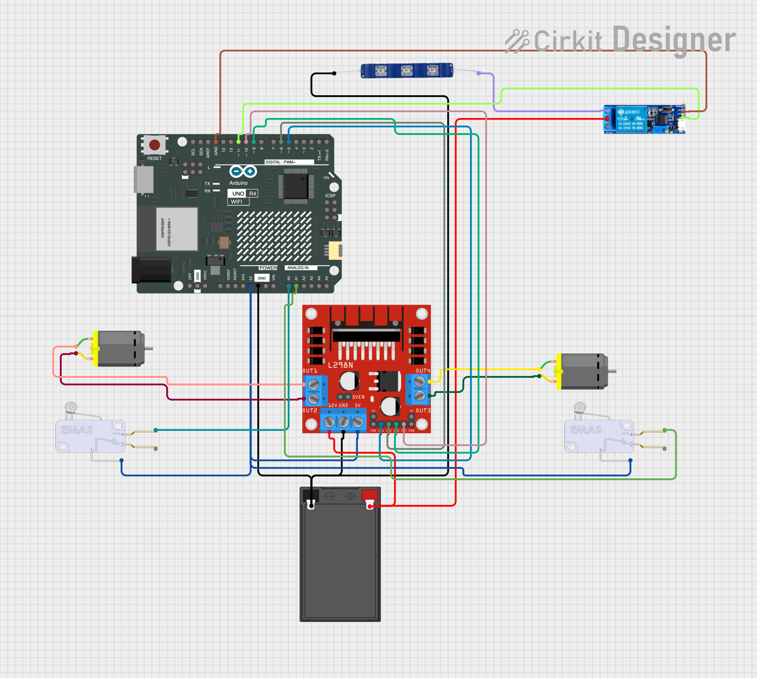
Circuit Documentation
Summary
This document provides a detailed overview of a circuit designed to control two DC motors using an Arduino UNO R4 WiFi microcontroller and an L298N DC motor driver. The circuit also includes endstops for position sensing, a relay module for controlling a 12V blue LED, and a battery for power supply.
Component List
Microcontroller
- Arduino UNO R4 WiFi: A microcontroller board based on the ATmega328, which includes WiFi capabilities. It is used as the central controller for the circuit, interfacing with sensors, driving the motor driver, and controlling the relay module.
Motor Driver
- L298N DC Motor Driver: A module capable of driving two DC motors. It receives control signals from the Arduino and powers the motors accordingly.
Endstops
- Endstop: A switch used to detect the presence or limit of an object. Two endstops are used in this circuit for position sensing.
Motors
- DC Motor: Two DC motors are included in the circuit, which are driven by the L298N motor driver.
Power Supply
- Battery: Provides the power source for the circuit, supplying 12V to the motor driver and through a relay to the LED.
Indicator
- 12V Blue LED: An indicator light that is controlled by the relay module.
Relay Module
- Relay Module 5V-30V: A module that allows the Arduino to control higher power circuits, such as the 12V blue LED.
Wiring Details
Arduino UNO R4 WiFi
- 5V: Connected to the 5V pins of the L298N motor driver and both endstops.
- GND: Common ground with the battery, 12V blue LED, L298N motor driver, and relay module.
- A0: Connected to the NO (Normally Open) pin of one endstop.
- A1: Connected to the NO (Normally Open) pin of the other endstop.
- D5: Sends control signal to IN1 on the L298N motor driver.
- D6: Sends control signal to IN2 on the L298N motor driver.
- D9: Sends control signal to IN3 on the L298N motor driver.
- D10: Sends control signal to IN4 on the L298N motor driver.
- D11: Controls the V+ on the relay module.
L298N DC Motor Driver
- 5V: Receives 5V from the Arduino and endstops.
- GND: Common ground with the battery, 12V blue LED, Arduino, and relay module.
- 12V: Connected to the positive terminal of the battery.
- OUT1/OUT2: Connected to the pins of one DC motor.
- OUT3/OUT4: Connected to the pins of the other DC motor.
Endstops
- Common: Both endstops share a common connection to the 5V line from the Arduino.
- NO: Each endstop's Normally Open pin is connected to a separate analog input on the Arduino (A0 and A1).
DC Motors
- Each motor has two pins connected to the respective OUT pins on the L298N motor driver.
Battery
- +: Connected to the 12V input on the L298N motor driver and the common contact of the relay module.
- -: Common ground with the 12V blue LED, L298N motor driver, Arduino, and relay module.
12V Blue LED
- VCC: Connected to the normally open contact of the relay module.
- GND: Common ground with the battery, L298N motor driver, Arduino, and relay module.
Relay Module 5V-30V
- V+: Controlled by D11 on the Arduino.
- V-: Common ground with the Arduino.
- Common Contact: Connected to the positive terminal of the battery.
- Normally Open: Connected to the VCC of the 12V blue LED.
Documented Code
void setup() {
  // put your setup code here, to run once:

}

void loop() {
  // put your main code here, to run repeatedly:

}
The provided code is a template with empty setup() and loop() functions. The setup() function is intended for initialization code that runs once when the microcontroller is powered on or reset. The loop() function contains the main logic of the program, which runs repeatedly as long as the microcontroller is powered. Specific functionality must be implemented within these functions to control the motors, read the endstops, and manage the relay module based on the requirements of the application.