Cirkit Designer
Your all-in-one circuit design IDE
Home /
Project Documentation
Arduino UNO Controlled Solenoid Actuation System with Relay and NPN Transistor

Circuit Documentation
Summary of the Circuit
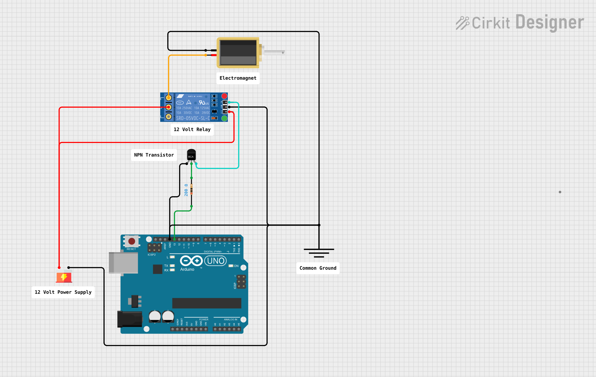
This circuit appears to be designed to control a solenoid using an Arduino UNO microcontroller and a KF-301 relay. The relay is driven by an NPN transistor, which is controlled by a digital output from the Arduino. A resistor is used to limit the current to the transistor's base. The power supply provides the necessary voltage to the relay and the solenoid. Ground connections are distributed among the components to complete the circuit.
Component List
Arduino UNO
- Description: A microcontroller board based on the ATmega328P.
- Purpose: Acts as the control unit for the circuit, providing logic signals to drive the relay.
- Pins: UNUSED, IOREF, Reset, 3.3V, 5V, GND, Vin, A0-A5, SCL, SDA, AREF, D13-D0.
NPN-Transistor
- Description: A bipolar junction transistor used as a switch or amplifier.
- Purpose: Amplifies the control signal from the Arduino to drive the relay.
- Pins: E (Emitter), C (Collector), B (Base).
Resistor
- Description: A passive two-terminal electrical component that implements electrical resistance.
- Purpose: Limits the current flowing into the transistor's base.
- Value: 200 Ohms.
Supply
- Description: Provides the required voltage for the circuit.
- Pins: VCC, GND.
Ground
- Description: A reference point in an electrical circuit from which voltages are measured.
- Pins: GND.
Solenoid
- Description: A coil wound into a tightly packed helix that produces a magnetic field when electric current is passed through it.
- Purpose: Actuates in response to the electrical signals controlled by the relay.
- Pins: pin1, pin2.
KF-301 Relay
- Description: An electromechanical switch used to control a high-power circuit with a low-power signal.
- Purpose: Allows the Arduino to control the solenoid indirectly.
- Pins: signal, power, ground, NC (Normally Closed), C (Common), NO (Normally Open).
Wiring Details
Arduino UNO
- GND connected to the common ground net.
- D13 connected to one end of the Resistor.
NPN-Transistor
- E (Emitter) connected to the common ground net.
- C (Collector) connected to one end of the Resistor.
- B (Base) connected to the signal pin of the KF-301 Relay.
Resistor
- One end connected to D13 on the Arduino UNO.
- The other end connected to the C (Collector) of the NPN-Transistor.
Supply
- VCC connected to the power pin of the KF-301 Relay and the C (Common) pin of the KF-301 Relay.
- GND connected to the common ground net.
Ground
- GND connected to the common ground net.
Solenoid
- One pin connected to the common ground net.
- The other pin connected to the NO (Normally Open) pin of the KF-301 Relay.
KF-301 Relay
- signal pin connected to the B (Base) of the NPN-Transistor.
- power pin connected to VCC of the Supply.
- ground pin connected to the common ground net.
- NO (Normally Open) pin connected to one pin of the Solenoid.
- C (Common) pin connected to VCC of the Supply.
Documented Code
Arduino UNO - sketch.ino
void setup() {
  // put your setup code here, to run once:

}

void loop() {
  // put your main code here, to run repeatedly:

}
Arduino UNO - documentation.txt
(No additional documentation provided for the code)
Please note that the actual functionality of the code is not provided in the given code snippet. The code will need to be completed with the logic to control the relay and, in turn, the solenoid.