
ESP8266 and GPS-RTK2 Based Real-Time GPS Tracker with Bluetooth and APC220 Communication
View and Edit Project In Cirkit Designer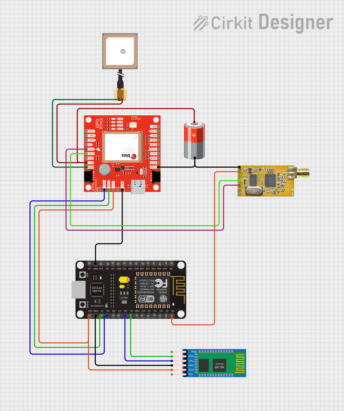
Circuit Documentation
Summary
This circuit integrates a GPS module, a Bluetooth module, a radio communication module, and a microcontroller (ESP8266 NodeMCU) to create a GPS tracking system. The GPS module provides location data, which is processed by the ESP8266. The processed data can be transmitted via Bluetooth or radio communication. The system is powered by a 5V battery.
Component List
SparkFun Qwiic GPS-RTK2 - ublox ZED-F9P
- Description: High-precision GPS module
- Pins: 1, TX2, RX2, 3.3V, 5, GND, SDA/!CS, SCL/SCK, FENCE_STAT, RTK_STAT, PPS, !RESET, !SAFE, INT, TXO/MISO, RXI/MOSI, 5V
esp8266 nodemcu
- Description: Wi-Fi microcontroller
- Pins: D0, D1, D2, D3, D4, 3V3, GND, D5, D6, D7, D8, RX, TX, A0, RSV, SD3, SD2, SD1, CMD, SD0, CLK, EN, RST, VIN
Antenna GPS Embedded SMA
- Description: GPS antenna
- Pins: VCC, GND
5V Battery
- Description: Power source
- Pins: +, -
HC-05 Bluetooth Module
- Description: Bluetooth communication module
- Pins: Key, VCC, GND, TXD, RXD, State
APC220
- Description: Radio communication module
- Pins: GND, VCC, EN, RXD, TXD, AUX, SET
Wiring Details
SparkFun Qwiic GPS-RTK2 - ublox ZED-F9P
- TX2 connected to RX of esp8266 nodemcu
- RX2 connected to TX of esp8266 nodemcu
- 3.3V connected to 3V3 of esp8266 nodemcu and VCC of HC-05 Bluetooth Module
- GND connected to GND of esp8266 nodemcu, GND of APC220, and GND of Antenna GPS Embedded SMA
- 5V connected to + of 5V Battery and VCC of Antenna GPS Embedded SMA
esp8266 nodemcu
- RX connected to TX2 of SparkFun Qwiic GPS-RTK2 - ublox ZED-F9P
- TX connected to RX2 of SparkFun Qwiic GPS-RTK2 - ublox ZED-F9P
- 3V3 connected to 3.3V of SparkFun Qwiic GPS-RTK2 - ublox ZED-F9P and VCC of HC-05 Bluetooth Module
- GND connected to GND of SparkFun Qwiic GPS-RTK2 - ublox ZED-F9P and GND of HC-05 Bluetooth Module
- D0 connected to VCC of APC220
- D5 connected to RXD of HC-05 Bluetooth Module
- D6 connected to TXD of HC-05 Bluetooth Module
Antenna GPS Embedded SMA
- VCC connected to 5V of SparkFun Qwiic GPS-RTK2 - ublox ZED-F9P
- GND connected to GND of SparkFun Qwiic GPS-RTK2 - ublox ZED-F9P
5V Battery
- + connected to 5V of SparkFun Qwiic GPS-RTK2 - ublox ZED-F9P and VCC of Antenna GPS Embedded SMA
- - connected to GND of APC220 and GND of SparkFun Qwiic GPS-RTK2 - ublox ZED-F9P
HC-05 Bluetooth Module
- VCC connected to 3.3V of esp8266 nodemcu and SparkFun Qwiic GPS-RTK2 - ublox ZED-F9P
- GND connected to GND of esp8266 nodemcu
- RXD connected to D5 of esp8266 nodemcu
- TXD connected to D6 of esp8266 nodemcu
APC220
- GND connected to - of 5V Battery and GND of SparkFun Qwiic GPS-RTK2 - ublox ZED-F9P
- TXD connected to RX2 of SparkFun Qwiic GPS-RTK2 - ublox ZED-F9P
- RXD connected to TX2 of SparkFun Qwiic GPS-RTK2 - ublox ZED-F9P
- VCC connected to D0 of esp8266 nodemcu
Documented Code
#include <SoftwareSerial.h>
#include <TinyGPS++.h>

// Define the RX and TX pins for Software Serial 2
#define RX 12
#define TX 14

#define GPS_BAUD 9600

// The TinyGPS++ object
TinyGPSPlus gps;

// Create an instance of Software Serial
SoftwareSerial gpsSerial(RX, TX);

void setup() {
  // Serial Monitor
  Serial.begin(115200);

  // Start Serial 2 with the defined RX and TX pins and a baud rate of 9600
  gpsSerial.begin(GPS_BAUD);
  Serial.println("Software Serial started at 9600 baud rate");
}

void loop() {
  // This sketch displays information every time a new sentence is correctly encoded.
  unsigned long start = millis();

  while (millis() - start < 1000) {
    while (gpsSerial.available() > 0) {
      gps.encode(gpsSerial.read());
    }
    if (gps.location.isUpdated()) {
      Serial.print("LAT: ");
      Serial.println(gps.location.lat(), 6);
      Serial.print("LONG: ");
      Serial.println(gps.location.lng(), 6);
      Serial.print("SPEED (km/h) = ");
      Serial.println(gps.speed.kmph());
      Serial.print("ALT (min)= ");
      Serial.println(gps.altitude.meters());
      Serial.print("HDOP = ");
      Serial.println(gps.hdop.value() / 100.0);
      Serial.print("Satellites = ");
      Serial.println(gps.satellites.value());
      Serial.print("Time in UTC: ");
      Serial.println(String(gps.date.year()) + "/" + String(gps.date.month()) + "/" + String(gps.date.day()) + "," + String(gps.time.hour()) + ":" + String(gps.time.minute()) + ":" + String(gps.time.second()));
      Serial.println("");
    }
  }
}
This code initializes the GPS module and reads the GPS data, which is then printed to the Serial Monitor. The data includes latitude, longitude, speed, altitude, HDOP, number of satellites, and the current time in UTC.