Cirkit Designer
Your all-in-one circuit design IDE
Home /
Project Documentation
Arduino Mega 2560 Fingerprint Authentication System with LED Feedback

Circuit Documentation
Summary of the Circuit
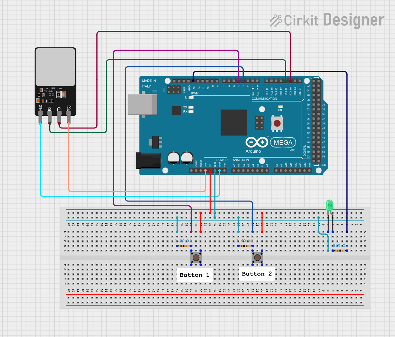
This circuit is designed around the Arduino Mega 2560 microcontroller, which serves as the central processing unit. The circuit includes a fingerprint scanner for biometric input, a green LED as an indicator, two pushbuttons as user inputs, and resistors for current limiting and pull-down configurations. The Arduino Mega 2560 communicates with the fingerprint scanner via serial communication and controls the LED based on the logic defined in the embedded code. The pushbuttons are used to trigger certain actions when pressed.
Component List
Arduino Mega 2560
- Description: A microcontroller board based on the ATmega2560.
- Pins: Multiple digital and analog I/O pins, power supply pins, and communication interface pins.
Fingerprint Scanner
- Description: A biometric sensor for scanning fingerprints.
- Pins: VCC, TX, RX, GND.
LED: Two Pin (green)
- Description: A green light-emitting diode.
- Pins: cathode, anode.
Resistor (220 Ohms)
- Description: A resistor with a resistance of 220 Ohms.
- Pins: pin1, pin2.
Resistor (1000 Ohms)
- Description: A resistor with a resistance of 1000 Ohms.
- Pins: pin1, pin2.
Pushbutton
- Description: A standard pushbutton switch.
- Pins: Pin 3 (out), Pin 4 (out), Pin 1 (in), Pin 2 (in).
Wiring Details
Arduino Mega 2560
- 3V3: Connected to the VCC of the Fingerprint Scanner.
- 5V: Connected to the Pin 3 (out) of both Pushbuttons.
- GND: Common ground shared with the LED, Resistors, and Fingerprint Scanner.
- D19/RX1: Connected to the TX of the Fingerprint Scanner.
- D18/TX1: Connected to the RX of the Fingerprint Scanner.
- D3 PWM: Connected to Pin 1 (in) of the first Pushbutton through a 1000 Ohm resistor.
- D4 PWM: Connected to Pin 1 (in) of the second Pushbutton through a 1000 Ohm resistor.
- D13 PWM: Connected to the pin2 of the 220 Ohm resistor.
Fingerprint Scanner
- VCC: Powered by the 3V3 output from the Arduino Mega 2560.
- TX: Sends data to the RX1 (D19) of the Arduino Mega 2560.
- RX: Receives data from the TX1 (D18) of the Arduino Mega 2560.
- GND: Connected to the common ground.
LED: Two Pin (green)
- cathode: Connected to the common ground.
- anode: Connected to the pin1 of the 220 Ohm resistor.
Resistor (220 Ohms)
- pin1: Connected to the anode of the LED.
- pin2: Connected to the D13 PWM of the Arduino Mega 2560.
Resistor (1000 Ohms)
- pin1: Connected to the common ground.
- pin2: Connected to the Pin 1 (in) of the corresponding Pushbutton and to the D3 PWM or D4 PWM of the Arduino Mega 2560.
Pushbutton
- Pin 3 (out): Powered by the 5V output from the Arduino Mega 2560.
- Pin 1 (in): Connected to the D3 PWM or D4 PWM of the Arduino Mega 2560 through a 1000 Ohm resistor.
Documented Code
Arduino Mega 2560 - sketch.ino
void setup() {
  // put your setup code here, to run once:

}

void loop() {
  // put your main code here, to run repeatedly:

}
Arduino Mega 2560 - documentation.txt
(No additional documentation provided)
This concludes the documentation for the provided circuit. The code for the Arduino Mega 2560 is currently a template and should be further developed to implement the desired functionality of the circuit.