
Arduino Nano-Based RS485 Communication Interface with LED Indicators
View and Edit Project In Cirkit Designer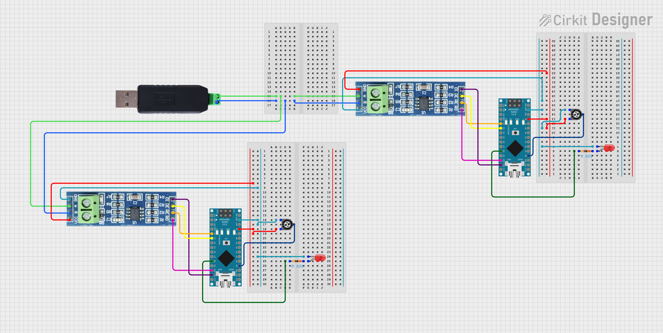
Circuit Documentation
Summary
The circuit in question is designed to interface an RS485 communication bus with an Arduino Nano microcontroller and includes signal conversion to USB for interfacing with a computer or other USB host. The circuit features two RS485 transceiver modules, each connected to a separate Arduino Nano. The Arduinos are responsible for handling the communication protocol and data processing. Additionally, the circuit includes two trimmer potentiometers for adjustable resistance, two LEDs with current-limiting resistors for indication purposes, and an RS485 to USB converter for direct communication with a USB host.
Component List
RS485 to USB Converter
- Description: Converts RS485 signals to USB for interfacing with a computer.
- Pins: A/TX, B/RX
Trimmer Potentiometer
- Description: Adjustable resistor for tuning and calibration.
- Pins: leg1, wiper, leg2
- Resistance: 10,000 Ohms
Resistor
- Description: Current-limiting resistor for LED protection.
- Pins: pin1, pin2
- Resistance: 220 Ohms
LED: Two Pin (red)
- Description: Red indicator light.
- Pins: cathode, anode
RS485 Transceiver
- Description: Module for RS485 communication.
- Pins: VCC, RO, RE, GND, B, A, DE, DI
Arduino Nano
- Description: Microcontroller for processing and control tasks.
- Pins: D1/TX, D0/RX, RESET, GND, D2 to D13, VIN, 5V, A0 to A7, AREF, 3V3
Wiring Details
RS485 to USB Converter
- A/TX connected to RS485 A lines
- B/RX connected to RS485 B lines
Trimmer Potentiometer (x2)
- leg1 connected to GND
- wiper connected to Arduino Nano A0
- leg2 connected to 5V
Resistor (x2)
- pin1 connected to LED anode
- pin2 connected to Arduino Nano D8
LED: Two Pin (red) (x2)
- cathode connected to GND through trimmer potentiometer leg1
- anode connected to resistor pin1
RS485 Transceiver (x2)
- VCC connected to 5V
- RO connected to Arduino Nano D10
- RE connected to Arduino Nano D2
- GND connected to GND
- B connected to RS485 B lines
- A connected to RS485 A lines
- DE connected to Arduino Nano D3
- DI connected to Arduino Nano D11/MOSI
Arduino Nano (x2)
- D1/TX, D0/RX for serial communication
- RESET, GND, D2 to D13 for control and interfacing
- VIN, 5V for power supply
- A0 to A7 for analog inputs
- AREF, 3V3 for reference voltages
Documented Code
Arduino Nano (Instance 1)
sketch.ino
void setup() {
  // put your setup code here, to run once:

}

void loop() {
  // put your main code here, to run repeatedly:

}
documentation.txt
(No additional documentation provided)
Arduino Nano (Instance 2)
sketch.ino
void setup() {
  // put your setup code here, to run once:

}

void loop() {
  // put your main code here, to run repeatedly:

}
documentation.txt
(No additional documentation provided)
This concludes the documentation for the given circuit. The code provided for both Arduino Nano instances is a template and does not contain any functional code specific to the circuit's operation. Additional code would be required to initialize the RS485 communication and handle data transmission and reception.