Cirkit Designer
Your all-in-one circuit design IDE
Home /
Project Documentation
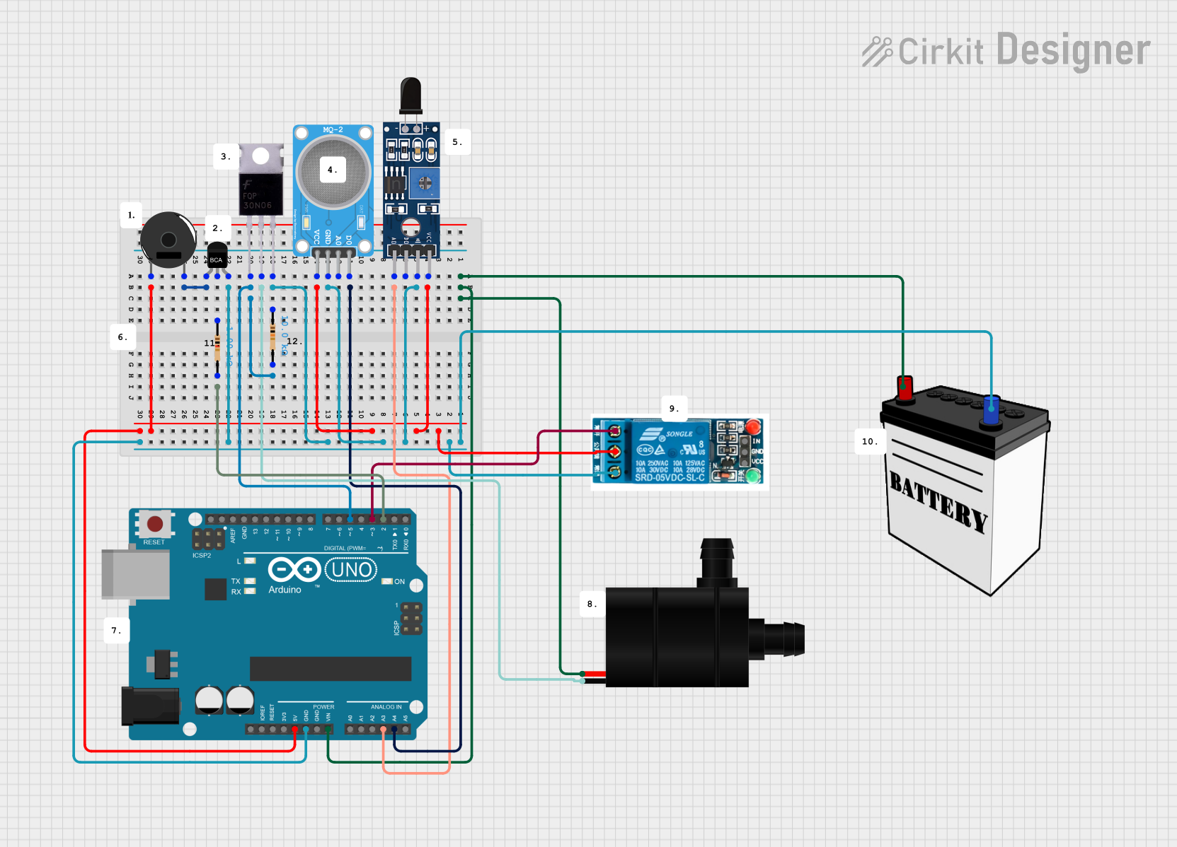
Arduino UNO-Based Fire and Gas Detection Safety System with Automated Water Pump Response
Circuit Documentation
Summary
This circuit is designed to interface various sensors, actuators, and control elements with an Arduino UNO microcontroller. The circuit includes gas and flame sensors for environmental monitoring, a piezo buzzer for audible alerts, a water pump for fluid control, a MOSFET and an NPN transistor for switching, resistors for current limiting and voltage division, a 5V relay for controlling higher power loads, and a 12V battery for power supply.
Component List
Sensors
- MQ-2 Gas Sensor: Detects various gases such as LPG, i-butane, methane, alcohol, Hydrogen, smoke.
- Sensor SHT113 Flame: Detects the presence of a flame or fire.
Actuators
- Piezo Buzzer: Emits an audible alert or tone.
- Water Pump: Pumps water when activated.
Control Elements
- Arduino UNO: A microcontroller board based on the ATmega328P, used for controlling the logic of the circuit.
- NPN-Transistor: A bipolar junction transistor used for switching or amplification.
- Mosfet: A type of field-effect transistor used for switching electronic signals.
- 5v Relay: An electromechanical switch used for turning on/off a circuit with a separate low-power signal.
Power Supply
- 12V Battery: Provides the power required for the circuit.
Passive Components
- Resistor (1k Ohm): Limits current or divides voltage in the circuit.
- Resistor (10k Ohm): Provides a pull-up or pull-down resistance or limits current.
Wiring Details
MQ-2 Gas Sensor
- VCC: Connected to the 5V supply from the Arduino UNO.
- GND: Connected to the ground net, shared with other components.
- A0: Not connected in this circuit.
- D0: Connected to the A4 pin on the Arduino UNO.
Sensor SHT113 Flame
- VCC: Connected to the 5V supply from the Arduino UNO.
- GND: Connected to the ground net, shared with other components.
- A0: Connected to the A3 pin on the Arduino UNO.
- D0: Not connected in this circuit.
Piezo Buzzer
- Pin 1: Connected to the 5V supply from the Arduino UNO.
- Pin 2: Connected to the emitter (E) of the NPN-Transistor.
Water Pump
- VCC: Connected to the Vin pin on the Arduino UNO and the VCC of the 12V Battery.
- GND: Connected to the drain (Drain) of the Mosfet.
NPN-Transistor
- E (Emitter): Connected to pin 2 of the Piezo Buzzer.
- C (Collector): Connected to pin 1 of a 1k Ohm Resistor.
- B (Base): Connected to pin 2 of a 10k Ohm Resistor and the ground net.
Mosfet
- Gate: Connected to pin D5 on the Arduino UNO and pin 2 of a 10k Ohm Resistor.
- Drain: Connected to the GND of the Water Pump.
- Source: Connected to the ground net.
Resistor (1k Ohm)
- Pin 1: Connected to the collector (C) of the NPN-Transistor.
- Pin 2: Not connected in this circuit.
Resistor (10k Ohm)
- Pin 1: Connected to the base (B) of the NPN-Transistor.
- Pin 2: Connected to the gate (Gate) of the Mosfet and pin D5 on the Arduino UNO.
5v Relay
- Normally Open (NO): Not connected in this circuit.
- Common Terminal (COM): Connected to the 5V supply from the Arduino UNO.
- Normally Closed (NC): Connected to the ground net.
- In: Not connected in this circuit.
- GND: Connected to the ground net.
- VCC: Connected to the 5V supply from the Arduino UNO.
12V Battery
- VCC: Connected to the Vin pin on the Arduino UNO and the VCC of the Water Pump.
- GND: Connected to the ground net.
Documented Code
Arduino UNO Code (sketch.ino)
void setup() {
  // put your setup code here, to run once:

}

void loop() {
  // put your main code here, to run repeatedly:

}
Note: The provided code is a template and does not contain any functional logic. It needs to be populated with the specific instructions to control the circuit based on the desired application.