
ESP32-Based Smart Home Sensor System with PIR Motion Detection and Environmental Monitoring
View and Edit Project In Cirkit Designer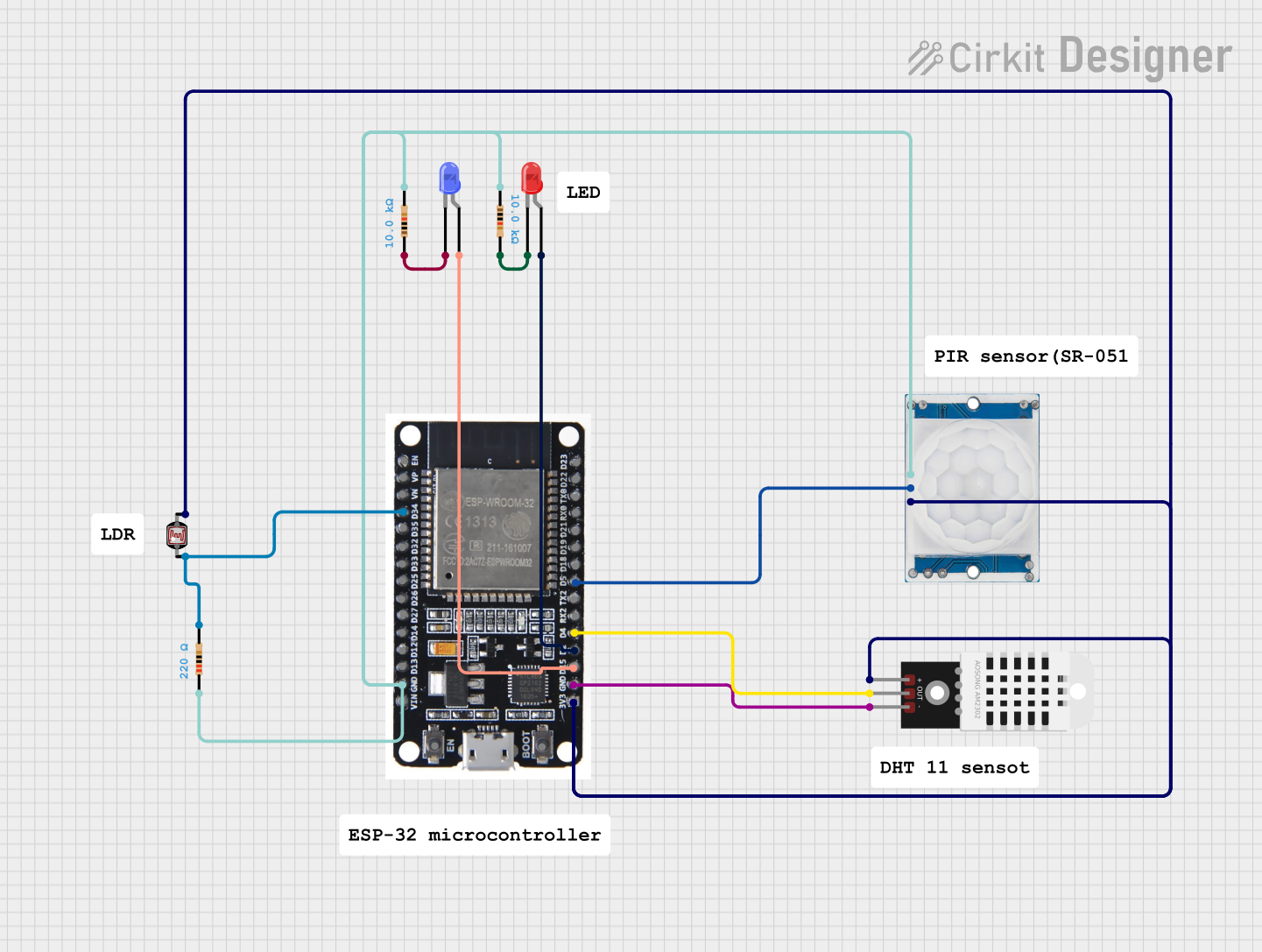
Circuit Documentation
Summary
This circuit is designed to interface an ESP32 microcontroller with various sensors and indicators. The ESP32 reads data from a PIR motion sensor, a DHT22 temperature and humidity sensor, and a photocell (LDR). It also controls two LEDs (one red and one blue) to indicate different states. The circuit includes resistors to limit current and ensure proper operation of the components.
Component List
HC-SR501 PIR Motion Sensor
- Pins: Output, Ground, Power Supply
- Description: Detects motion and outputs a signal when motion is detected.
ESP32
- Pins: EN, VP, VN, D34, D35, D32, D33, D25, D26, D27, D14, D12, D13, GND, VIN, 3V3, D15, D2, D4, RX2, TX2, D5, D18, D19, D21, RX0, TX0, D22, D23, BOOT
- Description: A powerful microcontroller with Wi-Fi and Bluetooth capabilities.
LED: Two Pin (red)
- Pins: Cathode, Anode
- Description: A red LED used for visual indication.
LED: Two Pin (blue)
- Pins: Cathode, Anode
- Description: A blue LED used for visual indication.
Resistor (10k Ohms)
- Pins: Pin1, Pin2
- Description: Limits current to protect components.
Resistor (220 Ohms)
- Pins: Pin1, Pin2
- Description: Limits current to protect components.
DHT22
- Pins: +, Out, -
- Description: Measures temperature and humidity.
Photocell (LDR)
- Pins: Pin 0, Pin 1
- Description: Measures light intensity.
Wiring Details
HC-SR501 PIR Motion Sensor
- Output connected to D5 of ESP32
- Ground connected to GND of ESP32 and pin2 of a 10k Ohm resistor
- Power Supply connected to 3V3 of ESP32
ESP32
- D5 connected to Output of HC-SR501 PIR Motion Sensor
- GND connected to Ground of HC-SR501 PIR Motion Sensor, - of DHT22, and pin2 of a 10k Ohm resistor
- 3V3 connected to Power Supply of HC-SR501 PIR Motion Sensor, + of DHT22, and pin 1 of Photocell (LDR)
- D34 connected to pin2 of a 220 Ohm resistor and pin 0 of Photocell (LDR)
- D15 connected to anode of LED: Two Pin (blue)
- D2 connected to anode of LED: Two Pin (red)
- D4 connected to Out of DHT22
LED: Two Pin (red)
- Anode connected to D2 of ESP32
- Cathode connected to pin2 of a 10k Ohm resistor
LED: Two Pin (blue)
- Anode connected to D15 of ESP32
- Cathode connected to pin1 of a 10k Ohm resistor
Resistor (10k Ohms)
- Pin1 connected to pin1 of another 10k Ohm resistor and pin2 of a 220 Ohm resistor
- Pin2 connected to Ground of HC-SR501 PIR Motion Sensor and GND of ESP32
Resistor (220 Ohms)
- Pin1 connected to pin1 of a 10k Ohm resistor
- Pin2 connected to D34 of ESP32 and pin 0 of Photocell (LDR)
DHT22
- + connected to 3V3 of ESP32
- Out connected to D4 of ESP32
- - connected to GND of ESP32
Photocell (LDR)
- Pin 0 connected to pin2 of a 220 Ohm resistor and D34 of ESP32
- Pin 1 connected to 3V3 of ESP32
Code
No code provided for this circuit.