
Circuit Documentation
Summary
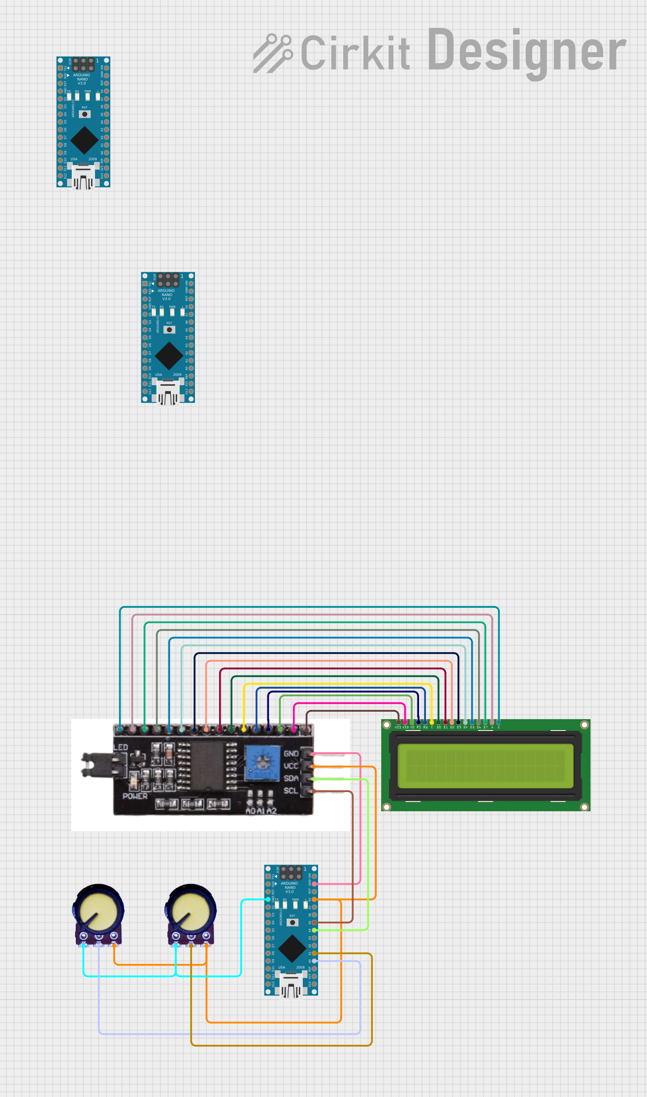
This circuit integrates multiple Arduino Nano microcontrollers with an LCD Display (16x2) through an I2C Module. The display's contrast is adjustable via two potentiometers. The Arduinos are responsible for controlling the behavior of the circuit, while the I2C Module facilitates communication between the LCD Display and one of the Arduino Nanos. The potentiometers are used to adjust parameters (likely contrast and/or backlight) of the LCD Display.
Component List
Microcontrollers
- Arduino Nano: A compact microcontroller board based on the ATmega328P, featuring digital and analog I/O pins.
Display
- LCD Display 16x2: A liquid crystal display capable of displaying 16 characters per line across 2 lines.
Modules
- I2C Module: An interface module that allows for serial communication over the I2C protocol, simplifying the connection between the LCD Display and the microcontroller.
Passive Components
- Potentiometer: A variable resistor with three terminals, used to adjust voltage and signal levels.
Wiring Details
Arduino Nano
- GND: Connected to the ground (GND) pins of the potentiometers and the I2C Module.
- 5V: Supplies power to the VCC pins of the potentiometers and the I2C Module.
- A4 (SDA): Connected to the SDA pin of the I2C Module for I2C communication.
- A5 (SCL): Connected to the SCL pin of the I2C Module for I2C communication.
- A0: Connected to the output of one potentiometer.
- A1: Connected to the output of the other potentiometer.
LCD Display 16x2
- LEDK, LEDA, DB7-DB0, E, RW, RS, VO, VDD, VSS: All connected to their respective pins on the I2C Module to facilitate communication and control.
I2C Module
- GND, VCC: Power connections shared with the Arduino Nano and potentiometers.
- SDA, SCL: I2C communication lines connected to the Arduino Nano.
- LEDK, LEDA, DB7-DB0, E, RW, RS, VO, VDD, VSS: Connected to the corresponding pins on the LCD Display to control it.
Potentiometers
- GND: Ground connection shared with the Arduino Nano.
- VCC: Power input shared with the Arduino Nano's 5V output.
- Output: One potentiometer output connected to A0 on the Arduino Nano, and the other to A1.
Documented Code
Arduino Nano (Primary Controller)
void setup() {
  // Initialization code here
}

void loop() {
  // Main code to run repeatedly
}
Note: The above code is a template and does not include specific functionality. It is expected that the user will add the necessary code to interact with the I2C module and the connected devices.
Arduino Nano (Secondary Controllers)
Note: The secondary Arduino Nanos do not have specific code provided for them. It is assumed that they will be programmed with code similar to the primary controller or with code that complements the primary controller's functionality.
This document provides a basic overview of the circuit's components, wiring, and code structure. For a complete and functional system, additional code must be written and uploaded to the Arduino Nanos to control the LCD Display via the I2C Module and to read the potentiometer values.