
Arduino UNO with MCP23017 IO Expansion and TTP233 Touch Sensors Interface
View and Edit Project In Cirkit Designer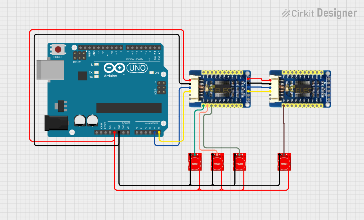
Circuit Documentation
Summary of the Circuit
This circuit is designed to interface an Arduino UNO with multiple TTP233 touch sensors through two MCP23017 I/O expansion boards. The Arduino UNO reads the state of the touch sensors and outputs a serial message indicating which sensor was activated. The touch sensors are powered by the 5V supply from the Arduino and are connected to the MCP23017 boards, which expand the number of input pins available to the Arduino. The MCP23017 boards communicate with the Arduino over the I2C bus.
Component List
Arduino UNO
- Microcontroller board based on the ATmega328P
- It has 14 digital input/output pins, 6 analog inputs, a 16 MHz quartz crystal, a USB connection, a power jack, an ICSP header, and a reset button.
MCP23017 I/O Expansion Board
- 16-bit I/O expander with I2C interface
- Provides 16 additional I/O pins for the microcontroller
- Each pin can be configured as an input or output
Touch Sensor TTP233
- Capacitive touch sensor module
- Operates as a touch-activated digital switch
- Has a single digital output that can be connected to a microcontroller pin
Wiring Details
Arduino UNO
5Vpin is connected to the VCC of all touch sensors and MCP23017 boards to provide power.GNDpin is connected to the GND of all touch sensors and MCP23017 boards to provide a common ground.A4(SDA) pin is connected to the SDA pin of the first MCP23017 board for I2C communication.A5(SCL) pin is connected to the SCL pin of the first MCP23017 board for I2C communication.
MCP23017 I/O Expansion Board
VCCpin is connected to the 5V supply from the Arduino UNO.GNDpin is connected to the ground of the Arduino UNO.SDApin is connected to the SDA pin (A4) on the Arduino UNO for I2C communication.SCLpin is connected to the SCL pin (A5) on the Arduino UNO for I2C communication.PB0,PB1,PB2pins are connected to the I/O pins of the touch sensors.
Touch Sensor TTP233
VCCpin is connected to the 5V supply from the Arduino UNO.GNDpin is connected to the ground of the Arduino UNO.I/Opin is connected to the corresponding PB pin on the MCP23017 board.
Documented Code
/*
 * This Arduino Sketch reads inputs from TTP223 touch sensors connected to
 * MCP23017 IO expansion boards. When a touch sensor is activated, the
 * Arduino sends a serial message indicating which sensor was activated.
 */

#include <Wire.h>
#include <Adafruit_MCP23017.h>

Adafruit_MCP23017 mcp1;
Adafruit_MCP23017 mcp2;

void setup() {
  Serial.begin(9600);
  Wire.begin();
  mcp1.begin(0); // Default address 0x20
  mcp2.begin(1); // Address 0x21

  // Initialize MCP23017 pins as inputs
  for (int i = 0; i < 3; i++) {
    mcp1.pinMode(i, INPUT);
    mcp2.pinMode(i, INPUT);
  }
}

void loop() {
  // Check sensors on MCP1
  for (int i = 0; i < 3; i++) {
    if (mcp1.digitalRead(i) == LOW) { // Assuming active low
      Serial.print("Sensor ");
      Serial.print(i + 1);
      Serial.println(" on MCP1 activated");
      delay(500); // Debounce delay
    }
  }

  // Check sensors on MCP2
  for (int i = 0; i < 1; i++) {
    if (mcp2.digitalRead(i) == LOW) { // Assuming active low
      Serial.print("Sensor ");
      Serial.print(i + 1);
      Serial.println(" on MCP2 activated");
      delay(500); // Debounce delay
    }
  }
}
The code initializes two MCP23017 instances and sets up the first three pins of each as inputs. In the main loop, it checks the state of these pins and prints a message to the serial monitor if a touch sensor connected to these pins is activated. The sensors are assumed to be active low, meaning they will be read as LOW when touched.