
Circuit Documentation
Summary
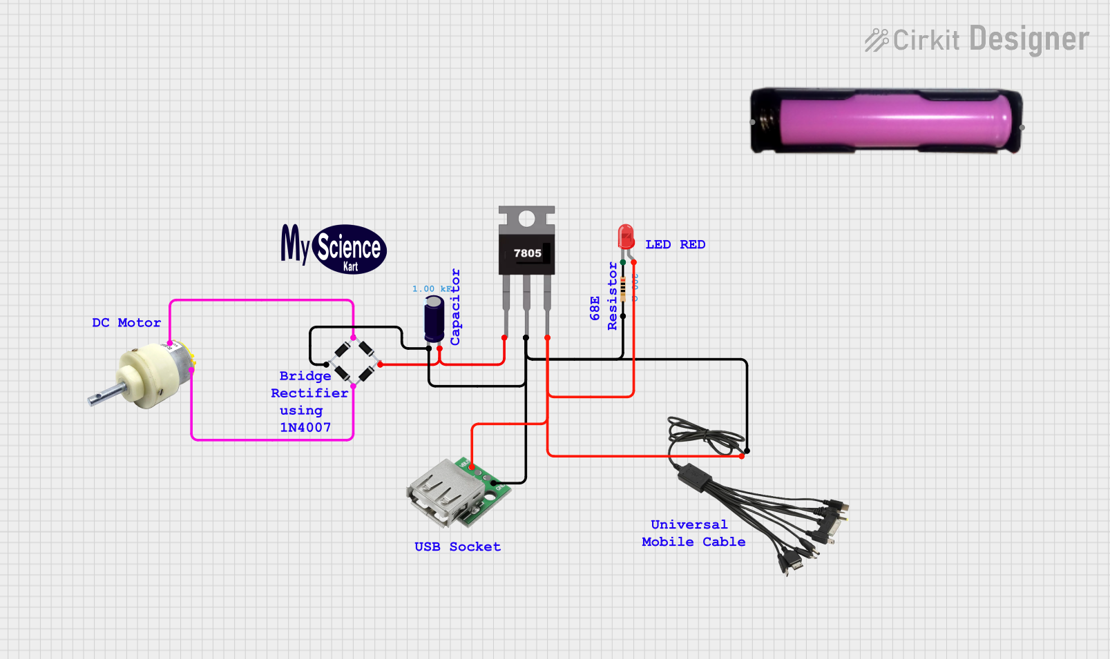
This document provides a detailed overview of a circuit that includes a DC gear motor, a bridge rectifier, an electrolytic capacitor, a 7805 voltage regulator, an LED, a resistor, a USB female connector, a multi-charging cable, and a 18650 battery holder. The circuit is designed to convert AC to DC, regulate the voltage, and provide a visual indication using an LED.
Component List
DC Gear Motor
- Pins: Positive, Negative
- Description: Converts electrical energy into mechanical energy.
- Purpose: Drives mechanical components in the circuit.
Bridge Rectifier
- Pins: Source_in-, Source_out-, Source_out+, Source_in+
- Description: Converts AC to DC.
- Purpose: Rectifies AC input to DC output.
Electrolytic Capacitor
- Pins: -, +
- Description: Stores electrical energy.
- Purpose: Smooths out the rectified DC voltage.
- Properties: Capacitance: 1000 Farads
7805 Voltage Regulator
- Pins: Vin, Gnd, Vout
- Description: Regulates voltage to 5V.
- Purpose: Provides a stable 5V output.
LED: Two Pin (red)
- Pins: Cathode, Anode
- Description: Emits light when current flows through it.
- Purpose: Provides visual indication.
Resistor
- Pins: Pin1, Pin2
- Description: Limits current flow.
- Purpose: Protects the LED from excessive current.
- Properties: Resistance: 200 Ohms
USB Female Connector
- Pins: VCC, GND, -D, +D
- Description: Provides a USB interface.
- Purpose: Allows connection to USB devices.
Multi Charging Cable Universal
- Pins: + Positive, - Negative
- Description: Provides multiple charging interfaces.
- Purpose: Supplies power to the circuit.
18650 Battery Holder
- Pins: GND, VCC
- Description: Holds a 18650 battery.
- Purpose: Provides power to the circuit.
Wiring Details
DC Gear Motor
- Positive connected to Bridge Rectifier Source_in+
- Negative connected to Bridge Rectifier Source_in-
Bridge Rectifier
- Source_in+ connected to DC Gear Motor Positive
- Source_in- connected to DC Gear Motor Negative
- Source_out- connected to:
- Multi Charging Cable Universal - Negative
- 7805 Voltage Regulator Gnd
- Electrolytic Capacitor -
- USB Female Connector GND
- Resistor Pin2
- Source_out+ connected to:
- 7805 Voltage Regulator Vin
- Electrolytic Capacitor +
Electrolytic Capacitor
- - connected to Bridge Rectifier Source_out-
- + connected to Bridge Rectifier Source_out+
7805 Voltage Regulator
- Vin connected to Bridge Rectifier Source_out+
- Gnd connected to Bridge Rectifier Source_out-
- Vout connected to:
- Multi Charging Cable Universal + Positive
- USB Female Connector VCC
- LED Anode
LED: Two Pin (red)
- Anode connected to 7805 Voltage Regulator Vout
- Cathode connected to Resistor Pin1
Resistor
- Pin1 connected to LED Cathode
- Pin2 connected to Bridge Rectifier Source_out-
USB Female Connector
- VCC connected to 7805 Voltage Regulator Vout
- GND connected to Bridge Rectifier Source_out-
Multi Charging Cable Universal
- + Positive connected to 7805 Voltage Regulator Vout
- - Negative connected to Bridge Rectifier Source_out-
18650 Battery Holder
- GND and VCC are not connected in this circuit.
Code
There is no code associated with this circuit.