
Arduino-Based AC Voltage Monitoring and Relay Control System
View and Edit Project In Cirkit Designer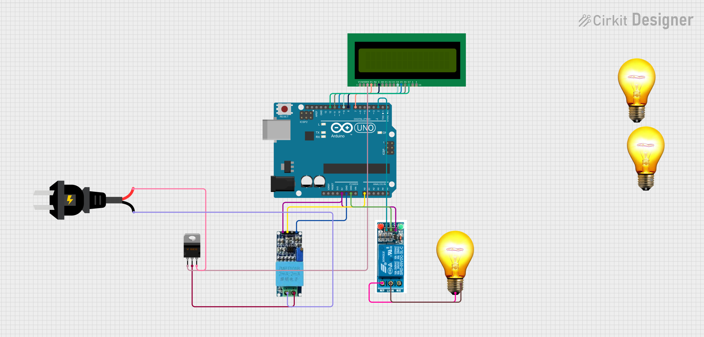
Circuit Documentation
Summary
The circuit is designed to monitor the voltage of an AC source and control an AC bulb accordingly. It uses an Arduino UNO microcontroller to read the voltage level from a voltage sensor and display the voltage on a 16x2 LCD. The Arduino controls a 5V relay to turn the AC bulb on or off based on the voltage level. If the voltage is outside the safe range (200V to 250V), the relay disconnects the bulb to prevent damage.
Component List
Voltage Sensor
- Description: Measures the AC voltage and outputs a corresponding signal.
- Pins: Ground, Phase, Vcc, Out, Gnd
AC Bulb
- Description: A standard AC bulb that lights up when powered.
- Pins: P (Phase), N (Neutral)
Arduino UNO
- Description: A microcontroller board based on the ATmega328P.
- Pins: UNUSED, IOREF, Reset, 3.3V, 5V, GND, Vin, A0-A5, SCL, SDA, AREF, D0-D13
5V Relay
- Description: An electromechanical switch used to control high power devices.
- Pins: Normally Open, Common terminal, Normally Closed, In, GND, VCC
AC Source
- Description: Provides the AC power for the circuit.
- Pins: + (Phase), - (Neutral)
16X2 LCD
- Description: A liquid crystal display for showing information.
- Pins: VSS, VDD, V0, RS, RW, E, D0-D7, A, K
Voltage Regulator - Variable
- Description: Adjusts the voltage to a desired level.
- Pins: ADJ, OUT, IN
Wiring Details
Voltage Sensor
- Vcc connected to 5V power supply.
- Ground connected to AC source neutral.
- Phase connected to the output of the voltage regulator.
- Out connected to the Arduino's A0 pin.
- Gnd connected to Arduino's GND.
AC Bulb
- P (Phase) connected to the Normally Open pin of the relay.
- N (Neutral) connected to the Common terminal pin of the relay.
Arduino UNO
- 5V pin provides power to the Voltage Sensor and 5V relay.
- GND pin connected to the GND of Voltage Sensor and 5V relay.
- A0 pin reads the output from the Voltage Sensor.
- D2 pin controls the relay In pin.
- D7-D12 pins connected to the 16X2 LCD.
5V Relay
- VCC connected to 5V power supply.
- GND connected to Arduino's GND.
- In controlled by Arduino's D2 pin.
- Normally Open connected to AC Bulb's P (Phase).
- Common terminal connected to AC Bulb's N (Neutral).
AC Source
-
- (Phase) connected to the IN pin of the voltage regulator.
-
- (Neutral) connected to the Ground pin of the voltage sensor.
16X2 LCD
- RS, E, D4-D7 pins connected to Arduino's D7, D8, D9, D10, D11, D12 respectively.
- V0 connected to the ADJ pin of the voltage regulator.
Voltage Regulator - Variable
- IN connected to the + (Phase) of the AC source.
- OUT connected to the Phase pin of the Voltage Sensor.
- ADJ connected to the V0 pin of the 16X2 LCD.
Documented Code
#include <LiquidCrystal.h>

// Initialize the LCD (RS, E, D4, D5, D6, D7)
LiquidCrystal lcd(7, 8, 9, 10, 11, 12);

const int voltagePin = A0;     // Analog pin for voltage sensor
const int relayPin = 2;        // Relay control pin

float minVoltage = 200.0;      // Minimum safe voltage
float maxVoltage = 250.0;      // Maximum safe voltage

void setup() {
  lcd.begin(16, 2);            // Initialize LCD
  pinMode(relayPin, OUTPUT);   // Relay control pin
  digitalWrite(relayPin, HIGH); // Ensure relay is off initially

  lcd.print("Voltage Monitor");
  delay(2000);
  lcd.clear();
}

void loop() {
  int sensorValue = analogRead(voltagePin);      // Read from AC sensor
  float voltage = sensorValue * (5.0 / 1023.0);  // Convert to 0-5V range
  voltage = voltage * (330.0 / 5.0);             // Scale to actual AC voltage

  lcd.setCursor(0, 0);
  lcd.print("Voltage: ");
  lcd.print(voltage);

  if (voltage < minVoltage) {
    lcd.setCursor(0, 1);
    lcd.print("Under Voltage! ");
    digitalWrite(relayPin, HIGH); // Turn off relay, disconnect load
  }
  else if (voltage > maxVoltage) {
    lcd.setCursor(0, 1);
    lcd.print("Over Voltage! ");
    digitalWrite(relayPin, HIGH); // Turn off relay, disconnect load
  }
  else {
    lcd.setCursor(0, 1);
    lcd.print("Voltage Normal ");
    digitalWrite(relayPin, LOW);  // Turn on relay, connect load
  }

  delay(500);
}
This code is designed to run on an Arduino UNO microcontroller. It initializes the LCD and sets up the relay and voltage sensor pins. In the main loop, it reads the voltage from the sensor, scales it to the AC voltage range, and displays it on the LCD. Depending on the voltage level, it controls the relay to protect the load from under or over-voltage conditions.