Cirkit Designer
Your all-in-one circuit design IDE
Home /
Project Documentation
Arduino UNO-Based Motion Detection System with PIR Sensors and Alert Indicators
Circuit Documentation
Summary
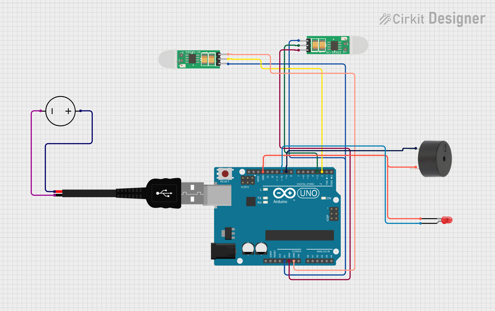
The circuit in question is designed to interface an Arduino UNO with a PIR (Passive Infrared) sensor, a buzzer, and an LED. The PIR sensor is used to detect motion, which can then trigger the LED and buzzer as indicators. The circuit is powered through a USB connection that also interfaces with a DC power source to ensure proper voltage levels. The Arduino UNO serves as the central processing unit, running the embedded code to control the behavior of the circuit based on the input from the PIR sensor.
Component List
Arduino UNO
- Microcontroller board based on the ATmega328P
- It has 14 digital input/output pins, 6 analog inputs, a 16 MHz quartz crystal, a USB connection, a power jack, an ICSP header, and a reset button.
PIR HC-SR505
- Mini PIR (Passive Infrared) motion sensor module
- Designed for detecting human body motion within a detection range.
Buzzer
- An electromechanical component that can be used to make noise or play tones.
LED: Two Pin (red)
- A basic red LED with an anode and cathode for indicating power or status.
USB male 2 pin connection
- A USB connector used for providing power to the circuit.
DC Power Source
- A power supply component that provides a stable voltage source for the circuit.
Wiring Details
Arduino UNO
- 5V connected to the positive (+) pin of both PIR sensors.
- GND connected to the negative (-) pin of both PIR sensors, the cathode of the LED, and the GND of the buzzer.
- D10 connected to the anode of the LED.
- D9 connected to the PIN of the buzzer.
- D3 connected to the output of the first PIR sensor.
- D2 connected to the output of the second PIR sensor.
PIR HC-SR505 (First Sensor)
- + connected to 5V on the Arduino UNO.
- out connected to D3 on the Arduino UNO.
- - connected to GND on the Arduino UNO.
PIR HC-SR505 (Second Sensor)
- + connected to 5V on the Arduino UNO.
- out connected to D2 on the Arduino UNO.
- - connected to GND on the Arduino UNO.
Buzzer
- PIN connected to D9 on the Arduino UNO.
- GND connected to GND on the Arduino UNO.
LED: Two Pin (red)
- anode connected to D10 on the Arduino UNO.
- cathode connected to GND on the Arduino UNO.
USB male 2 pin connection
- Positive + connected to the positive pin of the DC Power Source.
- Negative - connected to the ground pin of the DC Power Source.
DC Power Source
- Positive connected to the positive (+) pin of the USB connection.
- Ground connected to the negative (-) pin of the USB connection.
Documented Code
Arduino UNO Code (sketch.ino)
void setup() {
  // put your setup code here, to run once:

}

void loop() {
  // put your main code here, to run repeatedly:

}
Additional Notes
- The code provided for the Arduino UNO is a template and does not contain any functional code. It needs to be populated with the logic to read the PIR sensors and activate the buzzer and LED accordingly.
- The
setup()function is intended to initialize the pins and any libraries. - The
loop()function will contain the main logic that will be executed repeatedly.