
Arduino UNO Controlled Environmental Monitoring System with Multi-Sensor Integration
View and Edit Project In Cirkit Designer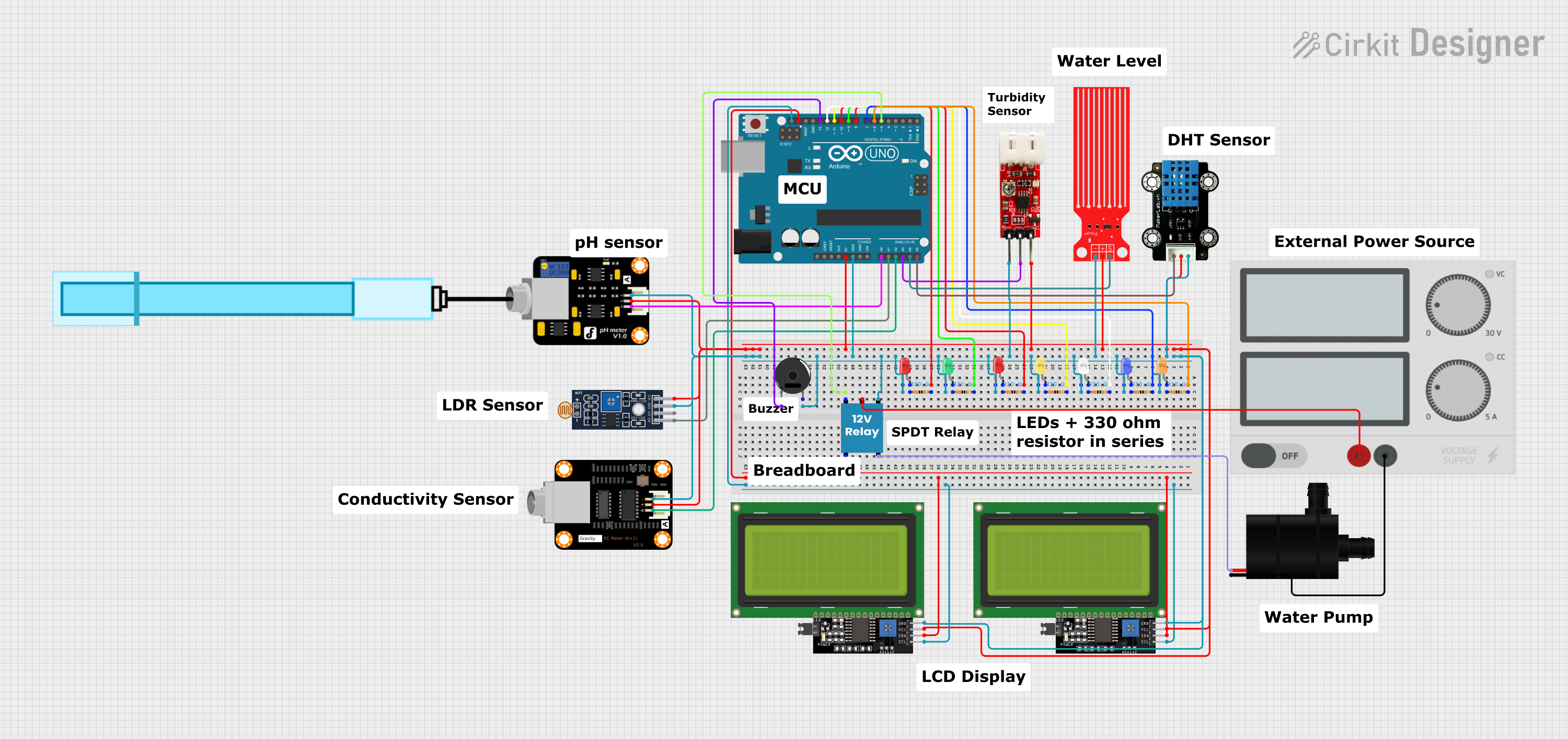
Circuit Documentation
Summary
This circuit is designed around an Arduino UNO microcontroller and includes various components such as LEDs, resistors, sensors, an LCD display, a piezo buzzer, a relay, a water pump, and a power supply. The circuit appears to be a monitoring and control system, potentially for an environmental or hydroponic setup, given the presence of sensors like the PH Meter, DFRobot EC Sensor, and Turbidity Module. The Arduino UNO controls the sensors and actuators, and the LCD displays system status.
Component List
- Arduino UNO: A microcontroller board based on the ATmega328P. It has digital input/output pins, analog inputs, a USB connection for programming, and power management features.
- Resistor (330 Ohms): A passive two-terminal electrical component that implements electrical resistance as a circuit element.
- LED (Red, Green, Yellow, White, Blue, Orange): Light Emitting Diodes of various colors used as indicators.
- LCD Display 20x4 I2C: A 20x4 character LCD display with an I2C interface for displaying text and characters.
- PH Meter: A sensor used to measure the acidity or alkalinity of a solution.
- Sensor LDR LM393: A light-dependent resistor sensor module with both analog and digital outputs.
- DFRobot EC Sensor: An electrical conductivity sensor used to measure the electrical conductivity in a solution.
- Turbidity Module: A sensor used to measure the turbidity (cloudiness) of a liquid.
- Water Level Sensor: A sensor used to detect the level of water in a tank or other container.
- MKE-S14 DHT11 Temperature And Humidity Sensor: A sensor used to measure ambient temperature and humidity.
- Water Pump: An electric pump used for moving water.
- Power Supply: Provides electrical power to the circuit.
- 12V Relay: An electrically operated switch that allows controlling a high-power circuit with a low-power signal.
- Piezo Buzzer: An electronic device that produces sound when an electrical signal is applied.
Wiring Details
Arduino UNO
- Digital Pins:
- D5: Connected to the 12V Relay (+)
- D6: Connected to a 330 Ohm Resistor
- D7: Connected to a 330 Ohm Resistor
- D8: Connected to a 330 Ohm Resistor
- D9: Connected to a 330 Ohm Resistor
- D10: Connected to a 330 Ohm Resistor
- D11: Connected to a 330 Ohm Resistor
- D12: Connected to a 330 Ohm Resistor
- D13: Connected to the Piezo Buzzer (pin 1)
- Analog Pins:
- A0: Connected to the PH Meter (Signal)
- A1: Connected to the Sensor LDR LM393 (A0)
- A2: Connected to the DFRobot EC Sensor (A)
- A3: Connected to the Turbidity Module (OUT)
- A4: Connected to the Water Level Sensor (SIG)
- A5: Connected to the MKE-S14 DHT11 Sensor (SIG)
- Power Pins:
- 5V: Connected to the LCD Displays (VCC), Sensors (VCC), and DHT11 Sensor (5V)
- GND: Connected to the LEDs (cathode), Piezo Buzzer (pin 2), LCD Displays (GND), Sensors (GND), and 12V Relay (-)
LEDs
- Each LED has its anode connected to a 330 Ohm Resistor and its cathode connected to the common ground.
LCD Display 20x4 I2C
- SCL: Connected to Arduino UNO (SCL)
- SDA: Connected to Arduino UNO (SDA)
- VCC: Connected to Arduino UNO (5V)
- GND: Connected to common ground
Sensors
- Each sensor is connected to its respective Arduino UNO analog input for signal and to the power supply lines for power and ground.
12V Relay
- C: Connected to the Power Supply (+)
- NO: Connected to the Water Pump (VCC)
- -: Connected to common ground
Water Pump
- GND: Connected to the Power Supply (-)
Power Supply
- +: Connected to the 12V Relay (C)
- -: Connected to the Water Pump (GND)
Documented Code
void setup() {
  // put your setup code here, to run once:

}

void loop() {
  // put your main code here, to run repeatedly:

}
The provided code is a template with empty setup() and loop() functions. The setup() function is intended for initialization code that runs once when the Arduino is powered on or reset. The loop() function contains the main logic of the program, which runs continuously as long as the Arduino is powered. Additional code is required to control the components based on the circuit's design and intended functionality.