Arduino UNO-Based Movement Detection and Alert System with MPU-6050, SIM800L, and LoRa Communication
Circuit Documentation
Summary
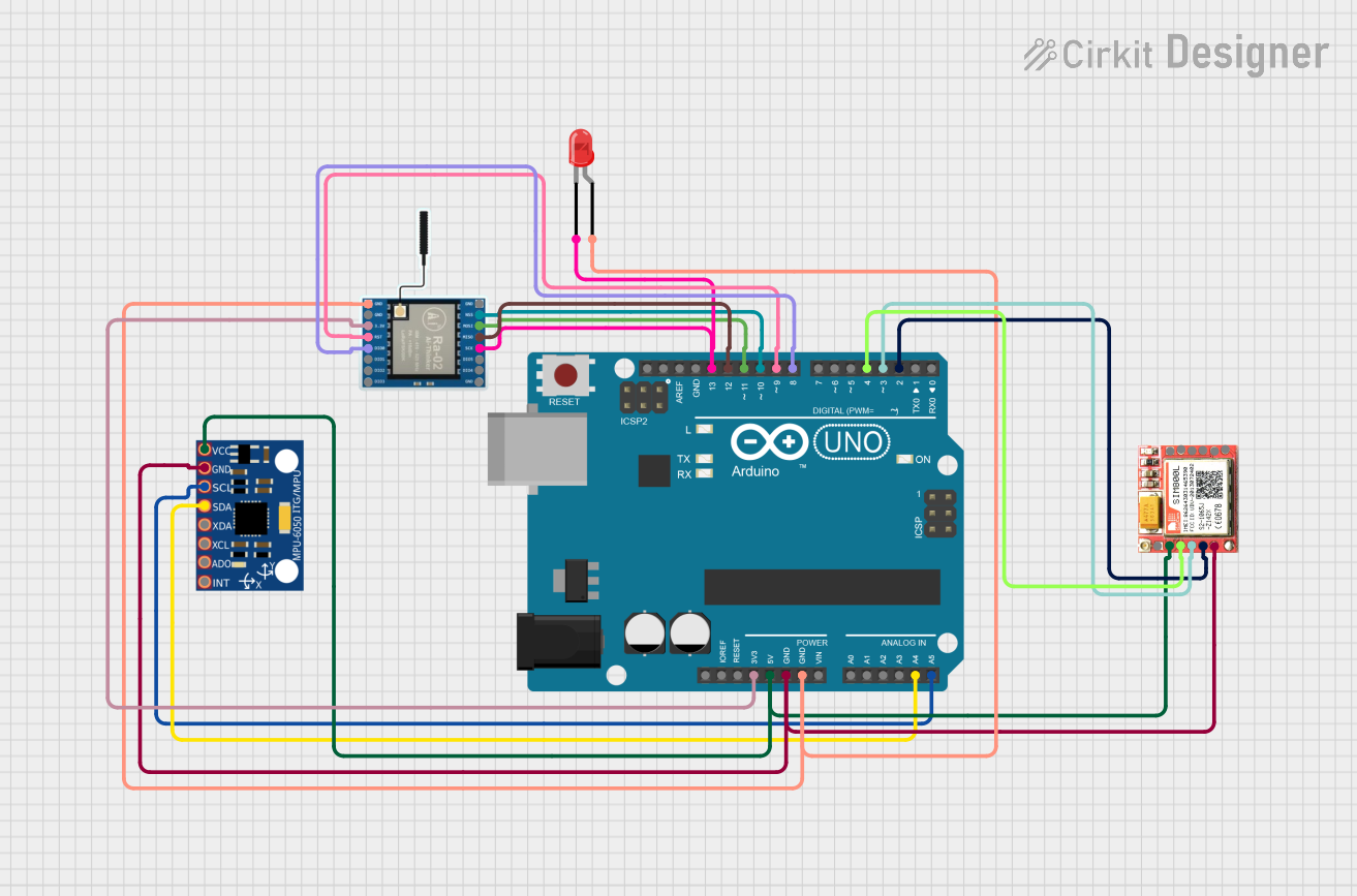
The circuit in question is designed around an Arduino UNO microcontroller and includes several peripheral components: an MPU-6050 accelerometer/gyroscope module, a SIM800L GSM module, a two-pin red LED, and a LoRa Ra-02 SX1278 module. The Arduino UNO serves as the central processing unit, interfacing with the MPU-6050 for motion detection, controlling the LED as an indicator, communicating with the SIM800L module for sending SMS messages, and handling LoRa communication through the SX1278 module.
Component List
Arduino UNO
- Microcontroller board based on the ATmega328P
- It has 14 digital input/output pins, 6 analog inputs, a 16 MHz quartz crystal, a USB connection, a power jack, an ICSP header, and a reset button.
MPU-6050
- A 6-axis motion tracking device that combines a 3-axis gyroscope and a 3-axis accelerometer on the same silicon die, along with an onboard Digital Motion Processor™ (DMP™) capable of processing complex 9-axis MotionFusion algorithms.
LED: Two Pin (red)
- A basic red LED with an anode and cathode for indicating statuses such as power or signal.
LoRa Ra-02 SX1278
- A wireless communication module that uses the LoRa (Long Range) protocol for long-distance data transmission.
SIM800L
- A GSM/GPRS module that allows for cellular network connectivity, enabling functions like SMS messaging and data transmission.
Wiring Details
Arduino UNO
3.3Vconnected to LoRa Ra-02 SX12783.3V5Vconnected to SIM800LVCCand MPU-6050VCC- Multiple
GNDpins connected to SIM800LGND, MPU-6050GND, LEDanode, and LoRa Ra-02 SX1278GND A4(SDA) connected to MPU-6050SDAA5(SCL) connected to MPU-6050SCLD13connected to LEDcathodeand LoRa Ra-02 SX1278SCKD12connected to LoRa Ra-02 SX1278MISOD11connected to LoRa Ra-02 SX1278MOSID10connected to LoRa Ra-02 SX1278NSSD9connected to LoRa Ra-02 SX1278RSTD8connected to LoRa Ra-02 SX1278DI00D4connected to SIM800LRSTD3connected to SIM800LRXDD2connected to SIM800LTXD
MPU-6050
VCCconnected to Arduino UNO5VGNDconnected to Arduino UNOGNDSCLconnected to Arduino UNOA5SDAconnected to Arduino UNOA4
LED: Two Pin (red)
anodeconnected to Arduino UNOGNDcathodeconnected to Arduino UNOD13
LoRa Ra-02 SX1278
3.3Vconnected to Arduino UNO3.3VGNDconnected to Arduino UNOGNDSCKconnected to Arduino UNOD13MISOconnected to Arduino UNOD12MOSIconnected to Arduino UNOD11NSSconnected to Arduino UNOD10RSTconnected to Arduino UNOD9DI00connected to Arduino UNOD8
SIM800L
VCCconnected to Arduino UNO5VGNDconnected to Arduino UNOGNDRSTconnected to Arduino UNOD4RXDconnected to Arduino UNOD3TXDconnected to Arduino UNOD2
Documented Code
#include <Wire.h>
#include <MPU6050.h>
#include <SoftwareSerial.h>

MPU6050 mpu;
SoftwareSerial sim800(2, 3); // RX, TX
const int ledPin = 13;
const int threshold = 1000; // Adjust this threshold as needed

void setup() {
  pinMode(ledPin, OUTPUT);
  Wire.begin();
  Serial.begin(9600);
  sim800.begin(9600);
  mpu.initialize();
  if (!mpu.testConnection()) {
    Serial.println("MPU6050 connection failed");
    while (1);
  }
  Serial.println("MPU6050 connection successful");

  // Check SIM800L initialization
  sim800.print("AT\r");
  delay(100);
  if (sim800.available()) {
    String response = sim800.readString();
    if (response.indexOf("OK") == -1) {
      Serial.println("SIM800L initialization failed");
      while (1);
    }
  } else {
    Serial.println("SIM800L not responding");
    while (1);
  }

  sendSMS("System Initialized");
}

void loop() {
  int16_t ax, ay, az;
  mpu.getAcceleration(&ax, &ay, &az);
  int magnitude = sqrt(ax * ax + ay * ay + az * az);
  if (magnitude > threshold) {
    blinkLED();
    sendSMS("Movement detected!");
    delay(5000); // Wait 5 seconds before checking again
  }
  delay(100);
}

void blinkLED() {
  digitalWrite(ledPin, HIGH);
  delay(500);
  digitalWrite(ledPin, LOW);
  delay(500);
}

void sendSMS(const char* message) {
  sim800.print("AT+CMGF=1\r");
  delay(100);
  sim800.print("AT+CMGS=\"+1234567890\"\r"); // Replace with your phone number
  delay(100);
  sim800.print(message);
  delay(100);
  sim800.write(26); // ASCII code for CTRL+Z
  delay(1000); // Increased delay to ensure message is sent

  // Check if the message was sent successfully
  if (sim800.available()) {
    String response = sim800.readString();
    if (response.indexOf("OK") == -1) {
      Serial.println("Failed to send SMS");
    } else {
      Serial.println("SMS sent successfully");
    }
  } else {
    Serial.println("No response from SIM800L");
  }
}
This code is designed to run on the Arduino UNO and interfaces with the MPU-6050 to detect motion, controls an LED as an indicator, communicates with the SIM800L module to send SMS messages, and sets up the initial state of the LoRa SX1278 module. The code includes initialization checks for both the MPU-6050 and SIM800L to ensure proper startup and functionality.