Cirkit Designer
Your all-in-one circuit design IDE
Home /
Project Documentation
Raspberry Pi and ESP8266 Wi-Fi Controlled LED Display with Photocell
Circuit Documentation
Summary
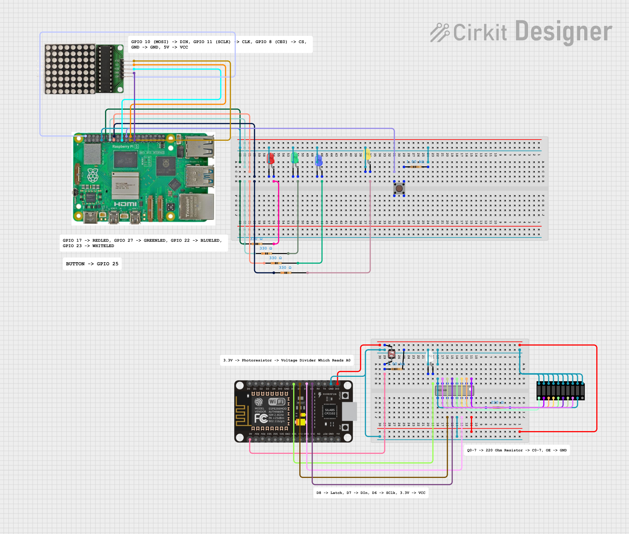
This circuit involves a Raspberry Pi 5, an ESP8266 NodeMCU, various LEDs, resistors, a pushbutton, a photocell (LDR), a 74HC595 shift register, a bar graph, and an LED matrix. The Raspberry Pi 5 and ESP8266 NodeMCU serve as the primary controllers, interfacing with the LEDs, pushbutton, and other components to create a functional and interactive system.
Component List
Raspberry Pi 5
- Pins: Type-C, Micro HDMI 1, Micro HDMI 2, Camera 1, Camera 2, PoE, Fan, PCIe, USB 3.0, USB 2.0, Ethernet, 5V, GND, 3.3v, GPIO 14, GPIO 15, GPIO 18, GPIO 23, GPIO 24, GPIO 25, GPIO 8, GPIO 7, GPIO 1, GPIO 12, GPIO 16, GPIO 20, GPIO 21, GPIO 2, GPIO 3, GPIO 4, GPIO 17, GPIO 27, GPIO 22, GPIO 10, GPIO 9, GPIO 11, GPIO 0, GPIO 5, GPIO 6, GPIO 13, GPIO 19, GPIO 26
- Description: A versatile single-board computer used for various applications.
- Purpose: Primary controller for the circuit.
ESP8266 NodeMCU
- Pins: D0, D1, D2, D3, D4, 3V3, GND, D5, D6, D7, D8, RX, TX, A0, RSV, SD3, SD2, SD1, CMD, SD0, CLK, EN, RST, VIN
- Description: A low-cost Wi-Fi microchip with full TCP/IP stack and microcontroller capability.
- Purpose: Secondary controller for the circuit.
LED: Two Pin (Red)
- Pins: Cathode, Anode
- Description: A red LED.
- Purpose: Visual indicator.
LED: Two Pin (Blue)
- Pins: Cathode, Anode
- Description: A blue LED.
- Purpose: Visual indicator.
LED: Two Pin (Green)
- Pins: Cathode, Anode
- Description: A green LED.
- Purpose: Visual indicator.
LED: Two Pin (Yellow)
- Pins: Cathode, Anode
- Description: A yellow LED.
- Purpose: Visual indicator.
LED: Two Pin (White)
- Pins: Cathode, Anode
- Description: A white LED.
- Purpose: Visual indicator.
Resistor (330 Ohms)
- Pins: Pin1, Pin2
- Description: A resistor with a resistance of 330 Ohms.
- Purpose: Current limiting for LEDs.
Resistor (1000 Ohms)
- Pins: Pin1, Pin2
- Description: A resistor with a resistance of 1000 Ohms.
- Purpose: Current limiting for various components.
Resistor (220 Ohms)
- Pins: Pin1, Pin2
- Description: A resistor with a resistance of 220 Ohms.
- Purpose: Current limiting for various components.
Pushbutton
- Pins: Pin 1 (in), Pin 2 (in), Pin 3 (out), Pin 4 (out)
- Description: A simple pushbutton.
- Purpose: User input.
Photocell (LDR)
- Pins: Pin 0, Pin 1
- Description: A light-dependent resistor.
- Purpose: Light sensing.
74HC595
- Pins: Q1, Q2, Q3, Q4, Q5, Q6, Q7, GND, VCC, Q0, DS (DATA), OE (Enable), ST_CP (RCLK), SH_CP (SRCLK), MR (SRCLR), Q7' (QH)
- Description: An 8-bit serial-in, serial or parallel-out shift register with output latches.
- Purpose: Extending GPIO pins.
Bar Graph (Wokwi Compatible)
- Pins: A1, A2, A3, A4, A5, A6, A7, A8, A9, A10, C8, C9, C10, C7, C6, C5, C4, C3, C2, C1
- Description: A bar graph display.
- Purpose: Visual display.
LED Matrix
- Pins: CLK, CS, DIN, GND, VCC
- Description: A matrix of LEDs.
- Purpose: Visual display.
Wiring Details
Raspberry Pi 5
- GND: Connected to the cathode of all LEDs (Red, Blue, Green, Yellow) and the GND pin of the LED Matrix.
- GPIO 25: Connected to Pin 1 (in) of the Pushbutton.
- GPIO 23: Connected to Pin1 of a 330 Ohm Resistor (Yellow LED).
- GPIO 22: Connected to Pin1 of a 330 Ohm Resistor (Blue LED).
- GPIO 27: Connected to Pin1 of a 330 Ohm Resistor (Green LED).
- GPIO 17: Connected to Pin1 of a 330 Ohm Resistor (Red LED).
- 5V: Connected to the VCC pin of the LED Matrix.
- GPIO 8: Connected to the CS pin of the LED Matrix.
- GPIO 10: Connected to the DIN pin of the LED Matrix.
- GPIO 11: Connected to the CLK pin of the LED Matrix.
ESP8266 NodeMCU
- 3V3: Connected to the VCC pin of the 74HC595 and pin 0 of the Photocell (LDR).
- GND: Connected to the GND pin of the 74HC595.
- D7: Connected to the DS (DATA) pin of the 74HC595.
- D8: Connected to the ST_CP (RCLK) pin of the 74HC595.
- D6: Connected to the SH_CP (SRCLK) pin of the 74HC595.
- D5: Connected to the anode of the White LED.
- A0: Connected to pin 1 of the Photocell (LDR).
LED: Two Pin (Red)
- Cathode: Connected to GND of Raspberry Pi 5.
- Anode: Connected to Pin2 of a 330 Ohm Resistor.
LED: Two Pin (Blue)
- Cathode: Connected to GND of Raspberry Pi 5.
- Anode: Connected to Pin2 of a 330 Ohm Resistor.
LED: Two Pin (Green)
- Cathode: Connected to GND of Raspberry Pi 5.
- Anode: Connected to Pin2 of a 330 Ohm Resistor.
LED: Two Pin (Yellow)
- Cathode: Connected to GND of Raspberry Pi 5.
- Anode: Connected to Pin2 of a 330 Ohm Resistor.
LED: Two Pin (White)
- Cathode: Connected to the OE (Enable) pin of the 74HC595.
- Anode: Connected to D5 of the ESP8266 NodeMCU.
Resistor (330 Ohms)
- Pin1: Connected to GPIO 23, GPIO 22, GPIO 27, and GPIO 17 of Raspberry Pi 5.
- Pin2: Connected to the anode of Red, Blue, Green, and Yellow LEDs.
Resistor (1000 Ohms)
- Pin1: Connected to Pin 3 (out) of the Pushbutton and pin 1 of the Photocell (LDR).
- Pin2: Connected to the OE (Enable) pin of the 74HC595.
Resistor (220 Ohms)
- Pin1: Connected to Pin 3 (out) of the Pushbutton.
- Pin2: Connected to the cathode of all LEDs (Red, Blue, Green, Yellow).
Pushbutton
- Pin 1 (in): Connected to GPIO 25 of Raspberry Pi 5.
- Pin 3 (out): Connected to Pin1 of a 1000 Ohm Resistor and Pin1 of a 220 Ohm Resistor.
Photocell (LDR)
- Pin 0: Connected to the VCC pin of the 74HC595.
- Pin 1: Connected to Pin1 of a 1000 Ohm Resistor and A0 of the ESP8266 NodeMCU.
74HC595
- Q1: Connected to C9 of the Bar Graph.
- Q2: Connected to C8 of the Bar Graph.
- Q3: