Arduino Mega ADK Controlled Vending Machine with I2C LCD Interface and Multiple DC Motors
Circuit Documentation
Summary
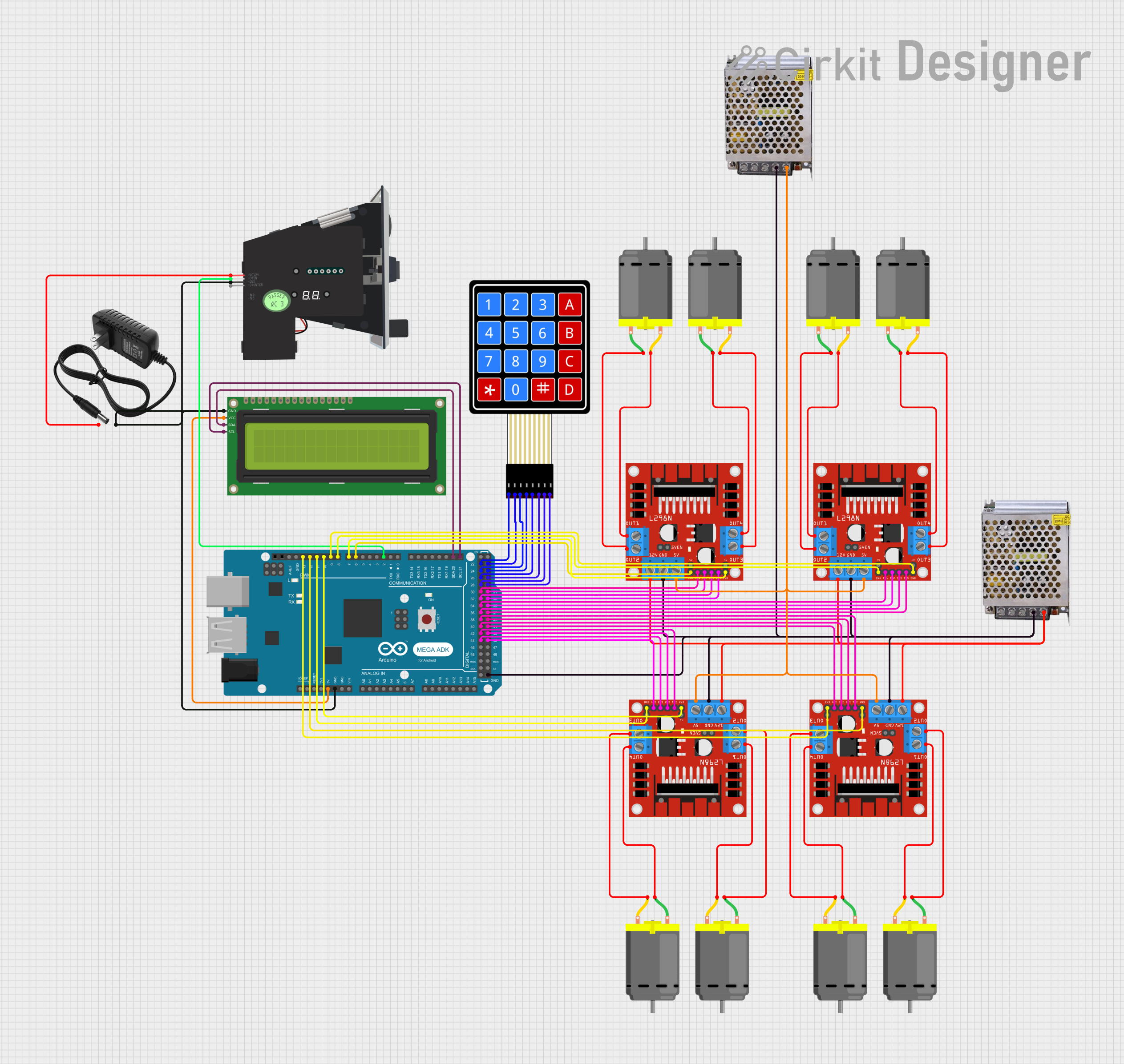
This circuit is designed to interface an Arduino Mega ADK (Rev3) with a variety of components including a 16x2 I2C LCD, multiple L298N DC motor drivers, a multi-coin acceptor, a 4x4 membrane matrix keypad, and several DC motors. The Arduino Mega ADK serves as the central controller, managing inputs from the keypad and coin acceptor, driving the motors through the motor drivers, and displaying information on the LCD. The circuit is powered by separate 12V and 5V power supplies, ensuring adequate power distribution for all components.
Component List
- Arduino Mega ADK (Rev3): A microcontroller board based on the ATmega2560, with numerous digital and analog I/O pins, communication interfaces, and a USB host interface for connecting compatible peripherals.
- 16x2 I2C LCD: A liquid crystal display with 16 characters by 2 lines, interfaced via the I2C protocol for displaying text or numbers.
- Multi Coin Acceptor: A device that can recognize multiple coin types for applications such as vending machines or arcade systems.
- 4X4 Membrane Matrix Keypad: A 16-button keypad arranged in a 4x4 matrix for user input.
- L298N DC Motor Driver: A high-power motor driver capable of driving DC motors with a supply voltage up to 46V and continuous current up to 2A per channel.
- POWER SUPPLY 12V 5AMP: A power supply unit that provides a 12V DC output with a maximum current of 5A.
- 12v Power Supply: A power supply unit that provides a 12V DC output.
- POWER SUPPLY 5V 5AMP: A power supply unit that provides a 5V DC output with a maximum current of 5A.
- DC Motor: A standard DC motor used for various mechanical movements in the circuit.
Wiring Details
Arduino Mega ADK (Rev3)
- I2C Communication:
D21/SCLconnected to 16x2 I2C LCDSCLD20/SDAconnected to 16x2 I2C LCDSDA
- Motor Driver Control:
D13 PWMto L298N (ENB)D12 PWMto L298N (ENA)D11 PWMto L298N (ENB)D10 PWMto L298N (ENA)D9 PWMto L298N (ENB)D8 PWMto L298N (ENA)D6 PWMto L298N (ENA)D7 PWMto L298N (ENB)D2 PWMto Multi Coin AcceptorCOIN
- Keypad Interface:
D22toR1D23toR2D24toR3D25toR4D26toC1D27toC2D28toC3D29toC4
- Motor Driver Inputs:
D30toIN1D31toIN2D32toIN3D33toIN4D34toIN1D35toIN2D36toIN3D37toIN4D38toIN1D39toIN2D40toIN3D41toIN4D42toIN1D43toIN2D44toIN3D45toIN4
- Power Connections:
5Vto 16x2 I2C LCDVCCGNDto 16x2 I2C LCDGND, Multi Coin AcceptorGND, and 12v power supply-
16x2 I2C LCD
SCLconnected to Arduino Mega ADKD21/SCLSDAconnected to Arduino Mega ADKD20/SDAVCCconnected to Arduino Mega ADK5VGNDconnected to Arduino Mega ADKGND
Multi Coin Acceptor
COINconnected to Arduino Mega ADKD2 PWMGNDconnected to Arduino Mega ADKGNDDC12Vconnected to 12v power supply+
4X4 Membrane Matrix Keypad
R1connected to Arduino Mega ADKD22R2connected to Arduino Mega ADKD23R3connected to Arduino Mega ADKD24R4connected to Arduino Mega ADKD25C1connected to Arduino Mega ADKD26C2connected to Arduino Mega ADKD27C3connected to Arduino Mega ADKD28C4connected to Arduino Mega ADKD29
L298N DC Motor Driver
- Multiple instances, each connected to Arduino Mega ADK for control signals (
ENA,ENB,IN1,IN2,IN3,IN4) GNDconnected to Arduino Mega ADKGND, POWER SUPPLY 5V 5AMPGND (DC), and POWER SUPPLY 12V 5AMPGND (DC)12Vconnected to POWER SUPPLY 12V 5AMP12V-24V Output (DC)5Vconnected to POWER SUPPLY 5V 5AMP12V-24V Output (DC)OUT1,OUT2,OUT3,OUT4connected to respective DC Motor pins
POWER SUPPLY 12V 5AMP
12V-24V Output (DC)connected to L298N DC motor drivers12VGND (DC)connected to L298N DC motor driversGND
12v Power Supply
+connected to Multi Coin AcceptorDC12V-connected to Arduino Mega ADKGND
POWER SUPPLY 5V 5AMP
12V-24V Output (DC)connected to L298N DC motor drivers5VGND (DC)connected to L298N DC motor driversGND
DC Motor
- Multiple instances, each connected to respective L298N DC motor driver outputs (
OUT1,OUT2,OUT3,OUT4)
Documented Code
No code was provided for the microcontrollers in the circuit. The documentation of the code would typically include descriptions of the functions, algorithms, and logic used to control the components in the circuit. It would also detail how the microcontroller interacts with the other components, such as reading inputs from the keypad, controlling the motor drivers, and updating the display on the LCD.