Cirkit Designer
Your all-in-one circuit design IDE
Home /
Project Documentation
Arduino-Controlled Ultrasonic Sensor with Relay-Activated Water Pump
Circuit Documentation
Summary of the Circuit
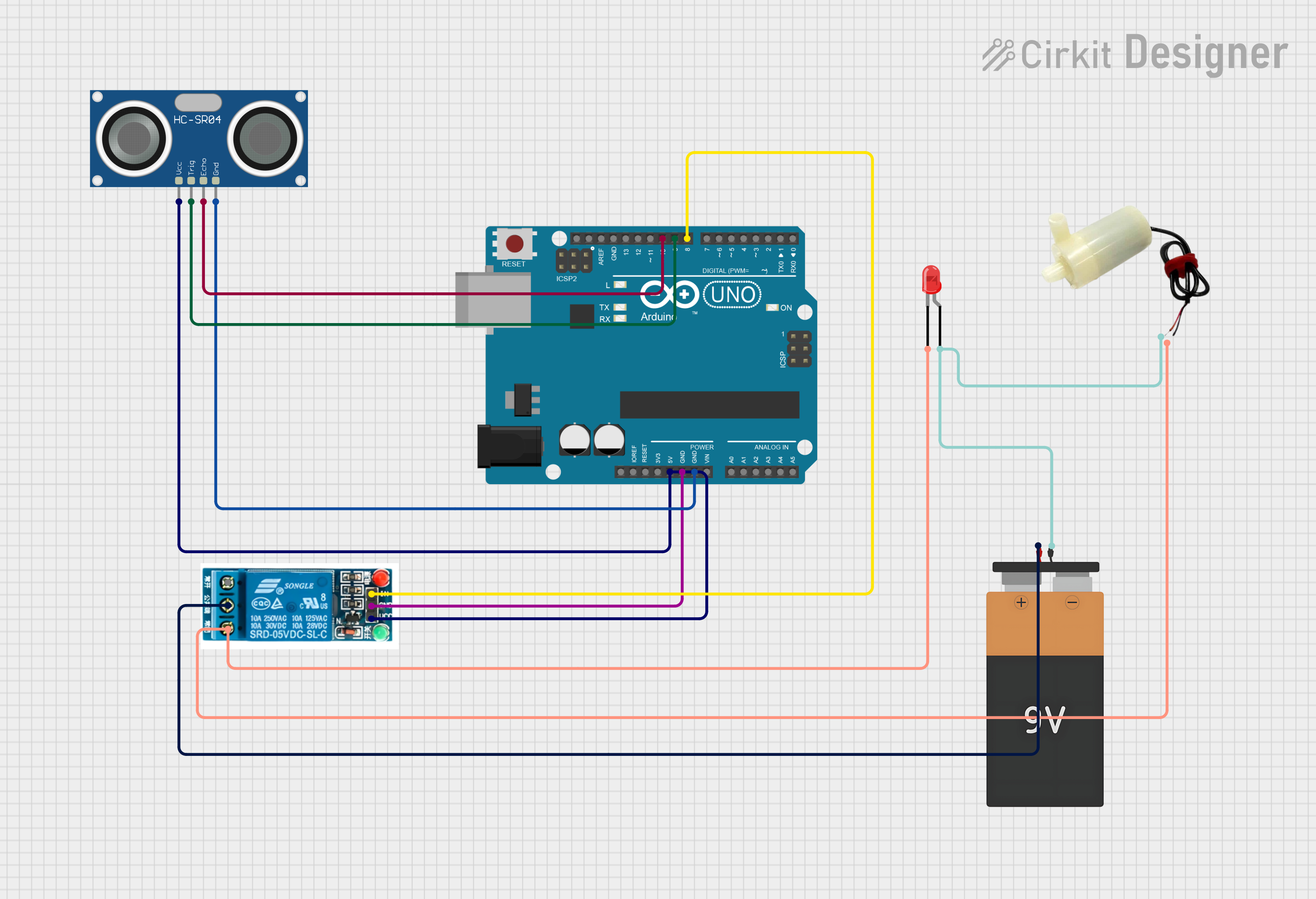
This circuit is designed to interface an Arduino UNO with an HC-SR04 Ultrasonic Sensor, a 5V relay, a 9V battery, an LED, and a 5V mini water pump. The Arduino UNO acts as the central controller, managing the sensor inputs and controlling the relay, which in turn controls the power to the LED and the water pump. The 9V battery provides power to the relay, and the Arduino UNO is used to power the sensor and the relay's control circuitry.
Component List
Arduino UNO
- Description: A microcontroller board based on the ATmega328P.
- Pins: UNUSED, IOREF, Reset, 3.3V, 5V, GND, Vin, A0-A5, SCL, SDA, AREF, D0-D13.
HC-SR04 Ultrasonic Sensor
- Description: An ultrasonic distance sensor.
- Pins: VCC, TRIG, ECHO, GND.
5V Relay
- Description: An electromechanical switch used to control a high power circuit with a low power signal.
- Pins: Normally Open, Common terminal, Normally Closed, In, GND, VCC.
Battery 9V
- Description: A standard 9V battery.
- Pins: VCC, GND.
LED: Two Pin (red)
- Description: A basic red LED.
- Pins: cathode, anode.
5V Mini Water Pump
- Description: A small water pump operating at 5V.
- Pins: positive pin, negative pin.
Wiring Details
Arduino UNO
- 5V: Connected to the VCC of the 5V relay and HC-SR04 Ultrasonic Sensor.
- GND: Connected to the GND of the 5V relay and HC-SR04 Ultrasonic Sensor.
- D10: Connected to the ECHO pin of the HC-SR04 Ultrasonic Sensor.
- D9: Connected to the TRIG pin of the HC-SR04 Ultrasonic Sensor.
- D8: Connected to the In pin of the 5V relay.
HC-SR04 Ultrasonic Sensor
- VCC: Connected to the 5V pin of the Arduino UNO.
- TRIG: Connected to the D9 pin of the Arduino UNO.
- ECHO: Connected to the D10 pin of the Arduino UNO.
- GND: Connected to the GND pin of the Arduino UNO.
5V Relay
- VCC: Connected to the 5V pin of the Arduino UNO.
- GND: Connected to the GND pin of the Arduino UNO.
- In: Connected to the D8 pin of the Arduino UNO.
- Common terminal: Connected to the VCC of the 9V Battery.
- Normally Closed: Connected to the cathode of the LED and the negative pin of the 5V mini water pump.
Battery 9V
- VCC: Connected to the Common terminal of the 5V relay.
- GND: Connected to the anode of the LED and the positive pin of the 5V mini water pump.
LED: Two Pin (red)
- cathode: Connected to the Normally Closed pin of the 5V relay.
- anode: Connected to the GND of the 9V Battery.
5V Mini Water Pump
- positive pin: Connected to the GND of the 9V Battery.
- negative pin: Connected to the Normally Closed pin of the 5V relay.
Documented Code
Arduino UNO Code (sketch.ino)
void setup() {
  // put your setup code here, to run once:

}

void loop() {
  // put your main code here, to run repeatedly:

}
Additional Notes (documentation.txt)
No additional code documentation provided.