Cirkit Designer
Your all-in-one circuit design IDE
Home /
Project Documentation
Arduino Mega 2560 and Raspberry Pi 4B Controlled WS2812 RGB LED Strip

Circuit Documentation
Summary
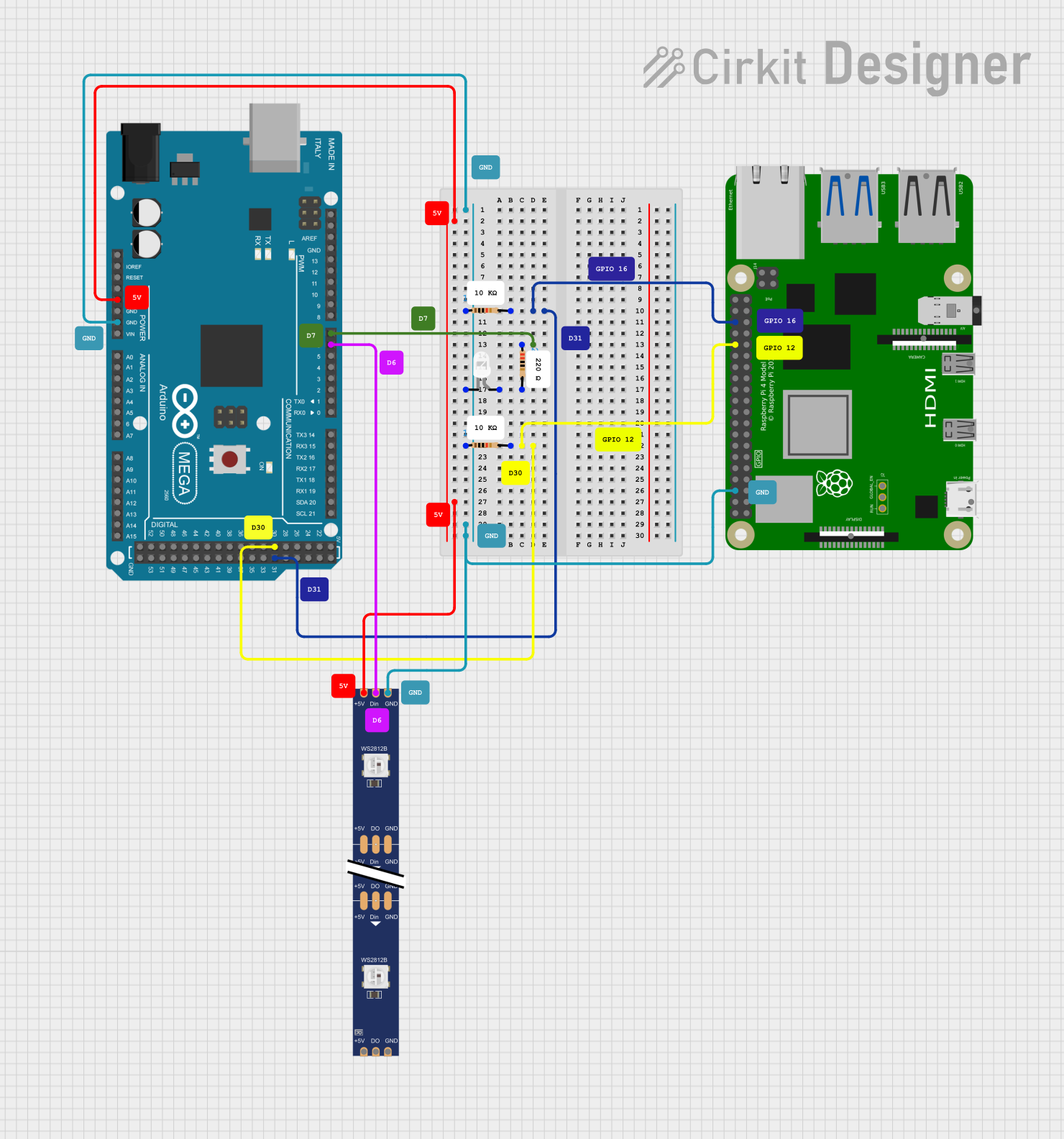
This circuit integrates an Arduino Mega 2560 with a Raspberry Pi 4B and controls a WS2812 RGB LED strip and a white LED. The Arduino Mega 2560 serves as the primary microcontroller for controlling the LEDs, while the Raspberry Pi 4B's role in the circuit is not explicitly defined in the provided information. The circuit includes resistors for current limiting and signal integrity purposes.
Component List
Microcontrollers
- Arduino Mega 2560: A microcontroller board based on the ATmega2560 with numerous digital and analog I/O pins.
- Raspberry Pi 4B: A small computer featuring a Broadcom processor with a variety of GPIO pins.
LEDs
- WS2812 RGB LED strip: An addressable LED strip that can display multiple colors and is controlled via a digital signal.
- LED: Two Pin (white): A standard white LED for indicating status or for simple lighting purposes.
Resistors
- 220 Ohm Resistor: Used for current limiting, possibly for the white LED.
- 10k Ohm Resistors: These resistors are likely used for pull-up or pull-down resistors in the circuit.
Wiring Details
Arduino Mega 2560
- Digital Pin 6 (PWM): Connected to the Data Input (DIN) of the WS2812 RGB LED strip.
- Digital Pin 7 (PWM): Connected to one end of a 220 Ohm resistor, with the other end connected to the anode of the white LED.
- Digital Pin 30: Connected to one end of a 10k Ohm resistor, with the other end connected to GPIO12 of the Raspberry Pi 4B.
- Digital Pin 31: Connected to one end of a 10k Ohm resistor, with the other end connected to GPIO16 of the Raspberry Pi 4B.
- 5V: Provides power to the WS2812 RGB LED strip.
- GND: Common ground for the Arduino, Raspberry Pi 4B, WS2812 RGB LED strip, and the white LED.
Raspberry Pi 4B
- GPIO12: Connected to a 10k Ohm resistor, with the other end connected to Digital Pin 30 of the Arduino Mega 2560.
- GPIO16: Connected to a 10k Ohm resistor, with the other end connected to Digital Pin 31 of the Arduino Mega 2560.
- GND: Common ground shared with the Arduino Mega 2560 and other components.
WS2812 RGB LED strip
- DIN: Receives data from Digital Pin 6 (PWM) of the Arduino Mega 2560.
- 5V: Powered by the 5V pin of the Arduino Mega 2560.
- GND: Connected to the common ground.
LED: Two Pin (white)
- Anode: Connected to a 220 Ohm resistor, with the other end connected to Digital Pin 7 (PWM) of the Arduino Mega 2560.
- Cathode: Connected to the common ground.
Resistors
- 220 Ohm Resistor: Connected between Digital Pin 7 (PWM) of the Arduino Mega 2560 and the anode of the white LED.
- 10k Ohm Resistors: Connected between the GPIO pins of the Raspberry Pi 4B and the digital pins of the Arduino Mega 2560.
Documented Code
Arduino Mega 2560
sketch.ino
void setup() {
  // put your setup code here, to run once:

}

void loop() {
  // put your main code here, to run repeatedly:

}
documentation.txt
No additional documentation provided for the code.
(Note: The code provided for the Arduino Mega 2560 is a template with no specific functionality. To control the WS2812 RGB LED strip and the white LED, additional code would be required to initialize the pins and to send data to the LED strip.)