Cirkit Designer
Your all-in-one circuit design IDE
Home /
Project Documentation
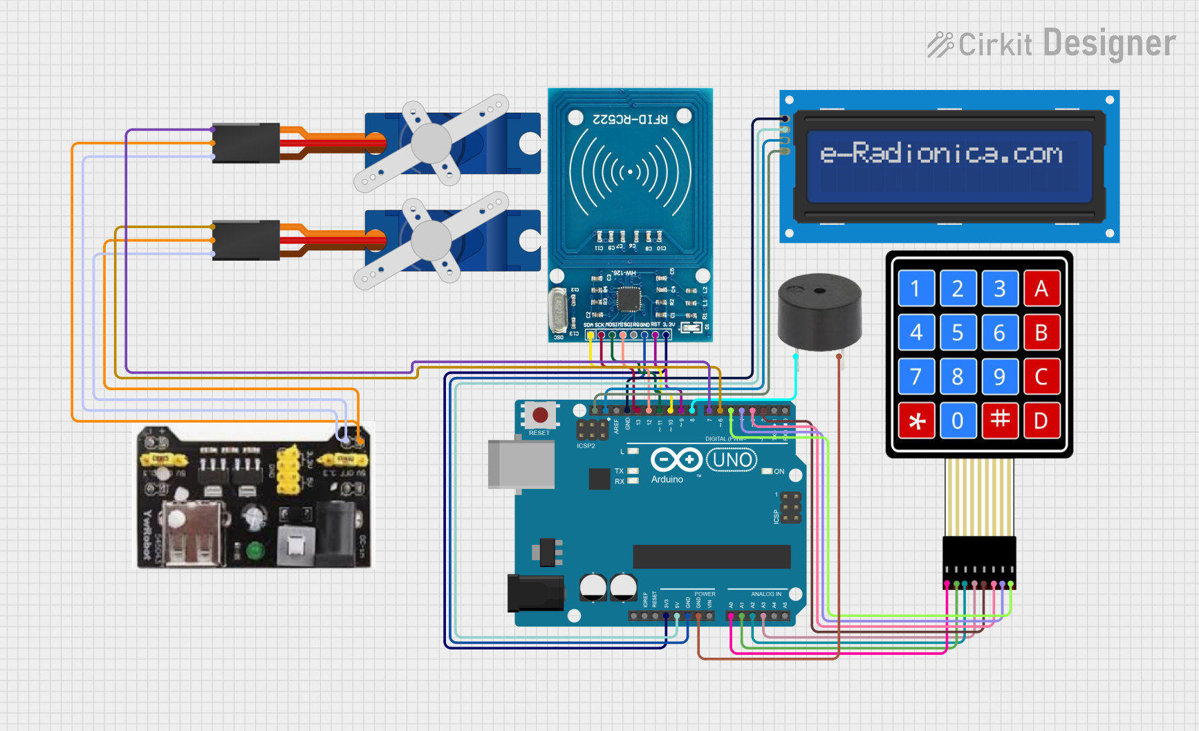
Arduino UNO RFID Access Control System with LCD Feedback and Servo Operation
Circuit Documentation
Summary
This document provides a detailed overview of a circuit designed to interface an RFID-RC522 module with an Arduino UNO. The circuit also includes an LCD screen for display, a 4x4 membrane matrix keypad for input, a buzzer for audio feedback, and two Tower Pro SG90 servos for actuation. The circuit is powered by an MB102 Breadboard Power Supply Module that provides both 3.3V and 5V outputs.
Component List
RFID-RC522
- Description: An RFID reader/writer module for contactless communication at 13.56MHz.
- Pins: VCC (3.3V), RST, GND, IRQ, MISO, MOSI, SCK, SDA
Arduino UNO
- Description: A microcontroller board based on the ATmega328P.
- Pins: UNUSED, IOREF, Reset, 3.3V, 5V, GND, Vin, A0-A5, SCL, SDA, AREF, D0-D13
LCD screen 16x2 I2C
- Description: A 16x2 character LCD display with an I2C interface.
- Pins: SCL, SDA, VCC, GND
4X4 Membrane Matrix Keypad
- Description: A 4x4 matrix keypad for user input.
- Pins: R1, R2, R3, R4, C1, C2, C3, C4
Buzzer
- Description: An electronic buzzer for audio signaling.
- Pins: PIN, GND
Tower Pro SG90 Servo (x2)
- Description: A small and lightweight servo motor for precise control.
- Pins: Signal, +5V, GND
MB102 Breadboard Power Supply Module 3.3V/5V
- Description: A power supply module for breadboards, providing both 3.3V and 5V outputs.
- Pins: GND, 3.3V, 5V
Wiring Details
RFID-RC522
- VCC (3.3V) connected to Arduino UNO 3.3V
- RST connected to Arduino UNO D9
- GND connected to Arduino UNO GND
- IRQ not connected
- MISO connected to Arduino UNO D12
- MOSI connected to Arduino UNO D11
- SCK connected to Arduino UNO D13
- SDA connected to Arduino UNO D10
Arduino UNO
- 3.3V connected to RFID-RC522 VCC (3.3V)
- 5V connected to LCD screen VCC
- GND connected to RFID-RC522 GND, buzzer GND, and LCD screen GND
- A0-A3 connected to 4X4 Membrane Matrix Keypad R1-R4 respectively
- SCL connected to LCD screen SCL
- SDA connected to LCD screen SDA
- D2-D5 connected to 4X4 Membrane Matrix Keypad C1-C4 respectively
- D6, D7 connected to Tower Pro SG90 servos' Signal pins
- D8 connected to buzzer PIN
- D9-D13 connected to RFID-RC522 RST, SDA, MOSI, MISO, SCK respectively
LCD screen 16x2 I2C
- SCL connected to Arduino UNO SCL
- SDA connected to Arduino UNO SDA
- VCC connected to Arduino UNO 5V
- GND connected to Arduino UNO GND
4X4 Membrane Matrix Keypad
- R1-R4 connected to Arduino UNO A0-A3 respectively
- C1-C4 connected to Arduino UNO D2-D5 respectively
Buzzer
- PIN connected to Arduino UNO D8
- GND connected to Arduino UNO GND
Tower Pro SG90 Servos
- Signal pins connected to Arduino UNO D6 and D7
- +5V pins connected to MB102 Breadboard Power Supply Module 5V
- GND pins connected to MB102 Breadboard Power Supply Module GND
MB102 Breadboard Power Supply Module 3.3V/5V
- 5V output connected to Tower Pro SG90 servos +5V
- GND output connected to Tower Pro SG90 servos GND
Documented Code
Arduino UNO Code (sketch.ino)
void setup() {
  // put your setup code here, to run once:

}

void loop() {
  // put your main code here, to run repeatedly:

}
Note: The provided code is a template and does not include any functionality. It should be populated with the necessary setup and loop code to control the components in the circuit.