
Circuit Documentation
Summary
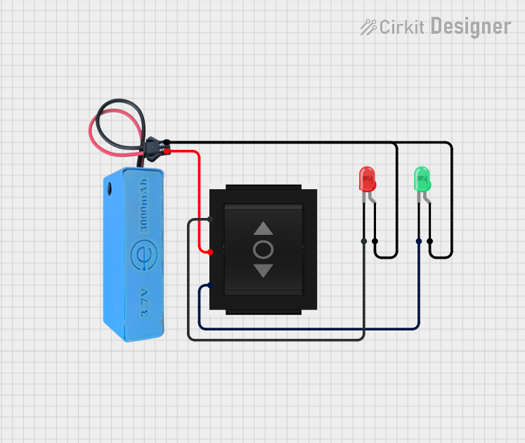
This circuit consists of two LEDs (one red and one green), a directional switch, and a power source (MAHIR 1.mini). The directional switch controls which LED is illuminated based on its position. The power source provides the necessary voltage to the circuit.
Component List
LED: Two Pin (red)
- Description: A red LED with two pins: cathode and anode.
- Purpose: Indicates the state of the circuit when the directional switch is in a specific position.
LED: Two Pin (green)
- Description: A green LED with two pins: cathode and anode.
- Purpose: Indicates the state of the circuit when the directional switch is in a specific position.
Directional Switch
- Description: A switch with three pins: IN, Out 1, and Out 2.
- Purpose: Controls the flow of current to either the red or green LED.
MAHIR 1.mini
- Description: A power source with two pins: GND and 3.7v.
- Purpose: Provides the necessary voltage to power the circuit.
Wiring Details
LED: Two Pin (red)
- Cathode: Connected to Out 1 of the Directional Switch.
- Anode: Connected to the GND of MAHIR 1.mini and the anode of the green LED.
LED: Two Pin (green)
- Cathode: Connected to Out 2 of the Directional Switch.
- Anode: Connected to the GND of MAHIR 1.mini and the anode of the red LED.
Directional Switch
- Out 1: Connected to the cathode of the red LED.
- Out 2: Connected to the cathode of the green LED.
- IN: Connected to the 3.7v of MAHIR 1.mini.
MAHIR 1.mini
- GND: Connected to the anode of both the red and green LEDs.
- 3.7v: Connected to the IN of the Directional Switch.
Code
There is no microcontroller code associated with this circuit.