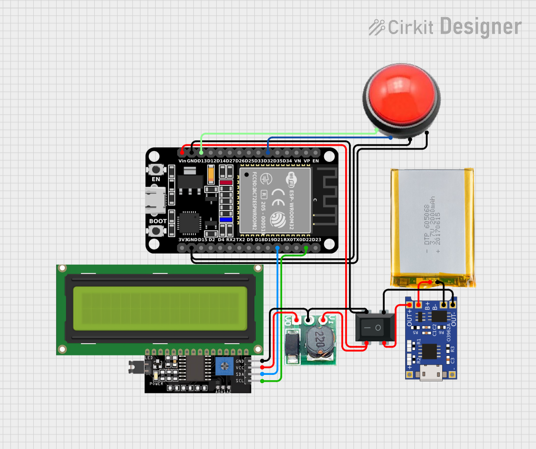
Battery-Powered ESP32 System with I2C LCD and Illuminated Button Control

Circuit Documentation
Summary
This circuit integrates various components including an ESP32 microcontroller, a TP4056 lithium battery charger module, an LCD Display with I2C interface, a Rocker Switch, an Arc Button with LED, a 2000mAh Battery, and a Step-Up Boost Converter. The ESP32 serves as the central processing unit, interfacing with the LCD Display for user output and the Arc Button for user input. The TP4056 module is used for charging the battery, which powers the circuit through the Step-Up Boost Converter, ensuring a stable voltage supply. The Rocker Switch acts as a power toggle for the circuit.
Component List
ESP32 (30 pin)
- Description: A microcontroller with Wi-Fi and Bluetooth capabilities, featuring a variety of GPIO pins for interfacing with peripherals.
- Purpose: Acts as the central processing unit for the circuit, handling input, output, and wireless communication.
TP4056
- Description: A lithium battery charger module with battery protection, designed for charging single-cell lithium-ion batteries.
- Purpose: Charges the 2000mAh battery and provides battery protection.
LCD Display 16x4 I2C
- Description: A 16x4 character LCD display with an I2C interface for simplified communication with the microcontroller.
- Purpose: Displays information to the user, interfaced with the ESP32 via I2C.
Rocker Switch 4 Pin
- Description: A simple on-off power switch with four pins.
- Purpose: Serves as the main power toggle for the circuit.
ArcBtnR
- Description: An arcade-style push button with an integrated LED.
- Purpose: Acts as a user input device and provides visual feedback through the LED.
2000mAh Battery
- Description: A rechargeable lithium-ion battery with a capacity of 2000mAh.
- Purpose: Provides power to the circuit when not connected to an external power source.
Step Up Boost 3v- 5v
- Description: A voltage step-up (boost) converter module that converts voltages from 3V to 5V.
- Purpose: Steps up the battery voltage to a stable 5V required by certain components in the circuit.
Wiring Details
ESP32 (30 pin)
- D32: Connected to ArcBtnR (VCC_BTN)
- D13: Connected to ArcBtnR (VCC_LED)
- GND: Common ground, connected to RockerSwitch4Pin (4), Step Up Boost 3v- 5v (GND), LCD Display 16x4 I2C (GND), and ArcBtnR (GND_LED, GND_BTN)
- Vin: Power input, connected to RockerSwitch4Pin (3) and Step Up Boost 3v- 5v (Vi)
- D22: Connected to LCD Display 16x4 I2C (SCL)
- D21: Connected to LCD Display 16x4 I2C (SDA)
TP4056
- B+: Connected to 2000mAh Battery (VCC)
- B-: Connected to 2000mAh Battery (GND)
- OUT-: Connected to RockerSwitch4Pin (2)
- OUT+: Connected to RockerSwitch4Pin (1)
LCD Display 16x4 I2C
- SCL: Connected to ESP32 (D22)
- SDA: Connected to ESP32 (D21)
- VCC: Connected to Step Up Boost 3v- 5v (Vo)
- GND: Common ground
Rocker Switch 4 Pin
- 1: Connected to TP4056 (OUT+)
- 2: Connected to TP4056 (OUT-)
- 3: Connected to ESP32 (Vin)
- 4: Common ground
ArcBtnR
- VCC_LED: Connected to ESP32 (D13)
- GND_LED: Common ground
- VCC_BTN: Connected to ESP32 (D32)
- GND_BTN: Common ground
2000mAh Battery
- VCC: Connected to TP4056 (B+)
- GND: Connected to TP4056 (B-)
Step Up Boost 3v- 5v
- Vi: Connected to RockerSwitch4Pin (3)
- GND: Common ground
- Vo: Connected to LCD Display 16x4 I2C (VCC)
Documented Code
There is no embedded code provided for the microcontrollers in the circuit. If code is later provided, it should be documented here with explanations for each function and routine, including setup and loop functions, interrupt service routines, and any libraries used for interfacing with peripherals such as the LCD Display or the Arc Button.