
Arduino UNO Controlled Robotic Arm with Bluetooth and Servo Motors
View and Edit Project In Cirkit Designer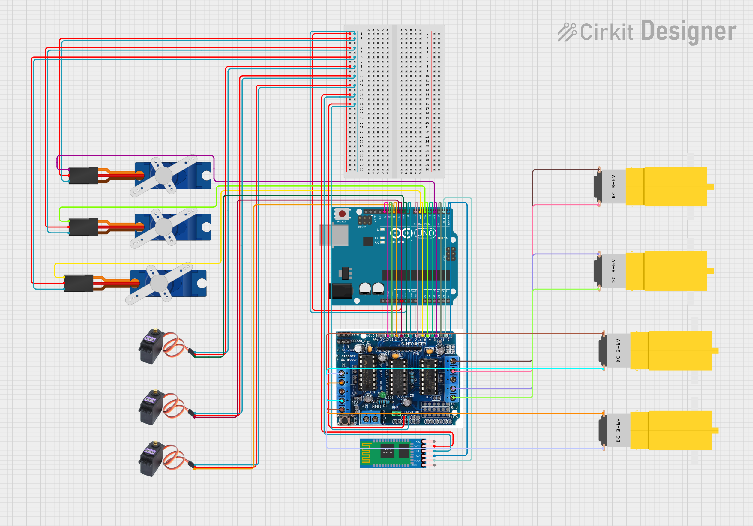
Circuit Documentation
Summary
This circuit is designed to control a series of servos and motors through an Arduino UNO microcontroller, which is also interfaced with an HC-05 Bluetooth module for wireless communication. The circuit includes a motor driver shield (l293d) to manage the power requirements and control signals for the motors. Power distribution is managed with common 5V and GND nets to supply the servos, the Bluetooth module, and the motor driver shield.
Component List
- Arduino UNO: A microcontroller board based on the ATmega328P. It has digital input/output pins, analog inputs, a USB connection for programming, and power management features.
- MG996R Servos (x3): High-torque digital servos for precise control of mechanical components.
- HC-05 Bluetooth Module: A wireless communication module that allows the Arduino to communicate with other Bluetooth-enabled devices.
- Hobby Motor Gearmotors (x4): Small DC motors with gear reduction for increased torque.
- Tower Pro SG90 Servos (x3): Compact and lightweight servos for controlling small mechanical systems.
- l293d Motor Driver Shield: An expansion board for Arduino that can control up to 4 DC motors with individual speed and direction control.
Wiring Details
Arduino UNO
- 5V: Connected to the +5V pins of all Tower Pro SG90 servos, MG996R servos, the HC-05 Bluetooth module, and the 5v pin of the l293d driver shield.
- GND: Connected to the GND pins of all Tower Pro SG90 servos, MG996R servos, the HC-05 Bluetooth module, and the gnd pin of the l293d driver shield.
- Digital Pins:
- D13: Connected to pin 12 of the l293d driver shield.
- D12: Connected to pin 12 of the l293d driver shield.
- D11: Connected to the SIG pin of an MG996R servo and pin 11 of the l293d driver shield.
- D10: Connected to the SIG pin of an MG996R servo and pin 10 of the l293d driver shield.
- D9: Connected to the SIG pin of an MG996R servo and pin 9 of the l293d driver shield.
- D8: Connected to pin 8 of the l293d driver shield.
- D7: Connected to pin 7 of the l293d driver shield.
- D6: Connected to the Signal pin of a Tower Pro SG90 servo and pin 6 of the l293d driver shield.
- D5: Connected to the Signal pin of a Tower Pro SG90 servo and pin 5 of the l293d driver shield.
- D4: Connected to pin 4 of the l293d driver shield.
- D3: Connected to the Signal pin of a Tower Pro SG90 servo and pin 3 of the l293d driver shield.
- D2: Connected to pin 2 of the l293d driver shield.
- D1: Connected to the RXD pin of the HC-05 Bluetooth module and pin 1 of the l293d driver shield.
- D0: Connected to the TXD pin of the HC-05 Bluetooth module and pin 0 of the l293d driver shield.
MG996R Servos
- VCC: Connected to the 5V net.
- GND: Connected to the GND net.
- SIG: Connected to the corresponding digital pins on the Arduino UNO (D9, D10, D11).
HC-05 Bluetooth Module
- VCC: Connected to the 5V net.
- GND: Connected to the GND net.
- TXD: Connected to D0 on the Arduino UNO.
- RXD: Connected to D1 on the Arduino UNO.
Hobby Motor Gearmotors
- vcc: Each motor's vcc pin is connected to the corresponding M+ pins on the l293d driver shield (M1, M2, M3, M4).
- GND: Each motor's GND pin is connected to the corresponding M- pins on the l293d driver shield (M1, M2, M3, M4).
Tower Pro SG90 Servos
- +5V: Connected to the 5V net.
- GND: Connected to the GND net.
- Signal: Connected to the corresponding digital pins on the Arduino UNO (D3, D5, D6).
l293d Motor Driver Shield
- 5v: Connected to the 5V net.
- gnd: Connected to the GND net.
- M1, M2, M3, M4: Connected to the corresponding Hobby Motor Gearmotors.
- Digital Pins (0-12): Connected to the corresponding digital pins on the Arduino UNO.
Documented Code
#include <Servo.h>

Servo servo1;
Servo servo2;
Servo servo3;
Servo servo4;
Servo servo5;
Servo servo6;

void setup() {
  // Attach servos to pins
  servo1.attach(3);
  servo2.attach(5);
  servo3.attach(6);
  servo4.attach(9);
  servo5.attach(10);
  servo6.attach(11);

  // Initialize motor driver pins
  pinMode(2, OUTPUT);
  pinMode(4, OUTPUT);
  pinMode(7, OUTPUT);
  pinMode(8, OUTPUT);

  // Initialize Bluetooth communication
  Serial.begin(9600);
}

void loop() {
  // Example: Move servos and control motors
  servo1.write(90);
  servo2.write(90);
  servo3.write(90);
  servo4.write(90);
  servo5.write(90);
  servo6.write(90);

  // Example: Control motors
  digitalWrite(2, HIGH);
  digitalWrite(4, LOW);
  digitalWrite(7, HIGH);
  digitalWrite(8, LOW);

  delay(1000);

  digitalWrite(2, LOW);
  digitalWrite(4, HIGH);
  digitalWrite(7, LOW);
  digitalWrite(8, HIGH);

  delay(1000);
}
This code is designed to initialize and control the servos and motors connected to the Arduino UNO. It sets up the servo objects, initializes the motor driver pins, and begins serial communication for the Bluetooth module. In the loop function, it provides an example of how to move the servos to a 90-degree position and how to control the motors by toggling the digital pins connected to the motor driver shield.