Cirkit Designer
Your all-in-one circuit design IDE
Home /
Project Documentation
ESP32-Based Smart Connectivity Hub with RFID and GPS Tracking
Circuit Documentation
Summary
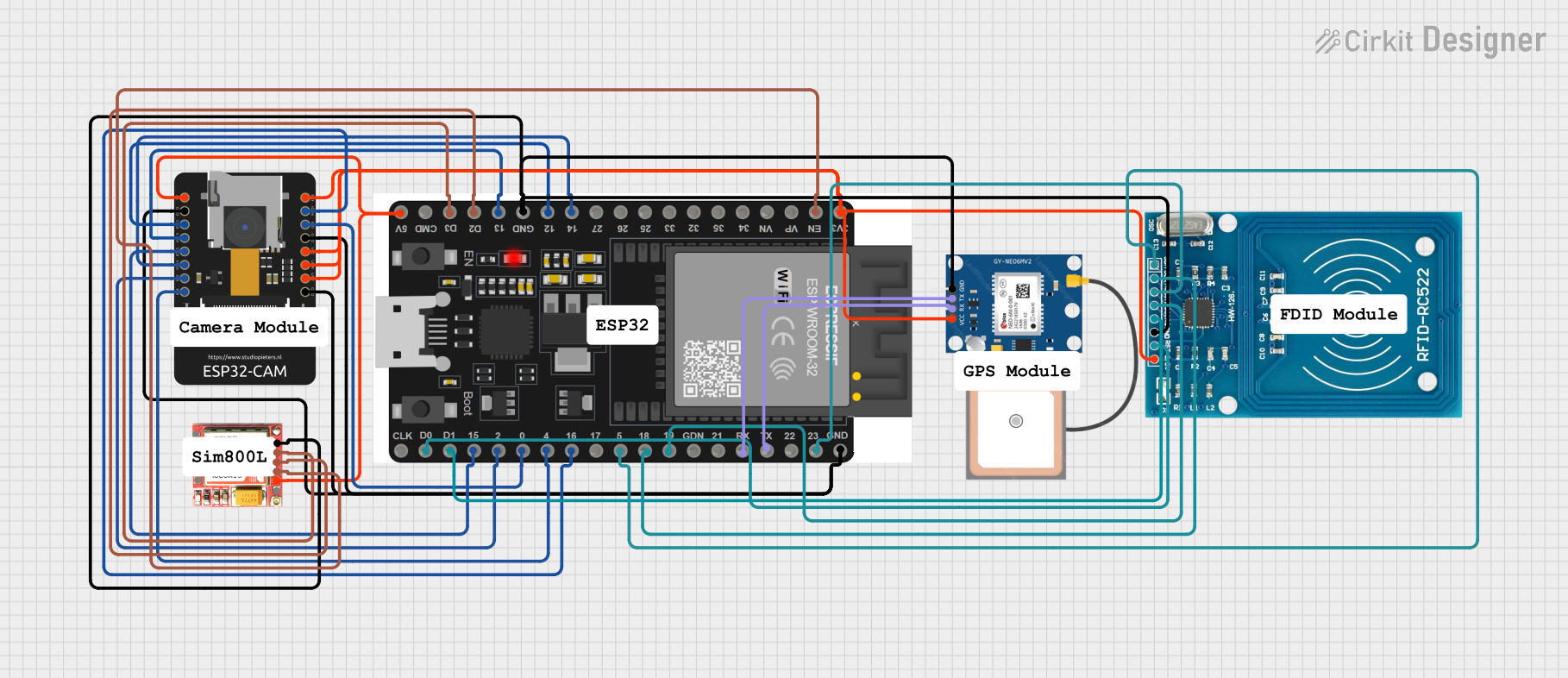
This circuit integrates various components to perform multiple functions, likely related to communication, identification, and location tracking. The primary microcontroller is an ESP32 with 38 pins, which interfaces with an ESP32-CAM module, an RFID-RC522 module for RFID communication, a SIM800L module for GSM cellular communication, and a GPS NEO 6M module for location tracking. The circuit is designed to allow the ESP32 to communicate with these modules and possibly process and relay data from them.
Component List
ESP32 38 PINS
- Description: A microcontroller with Wi-Fi and Bluetooth capabilities.
- Pins: GND, 23, 22/SCL, 1, 2, 21/SDA, 19, 18, 5, 17/TX2, 16/RX2, 4, 0, 15, D1, D0, CLK, 3V3, EN, VP, VN, 34, 35, 32, 33, 25, 26, 27, 14, 12, 13, D2, D3, 11, 5V/VIN
ESP32 - CAM
- Description: A camera module with Wi-Fi capabilities.
- Pins: 5V, GND, IO12, IO13, IO15, IO14, IO2, IO4, VOT, VOR, VCC, IO0, IO16, 3V3
RFID-RC522
- Description: An RFID reader/writer module.
- Pins: VCC (3.3V), RST, GND, IRQ, MISO, MOSI, SCK, SDA
SIM800L
- Description: A GSM/GPRS module.
- Pins: NFT, RING, VCC, DTR, RST, MIC +, RXD, MIC-, TXD, SPK+, GND, SPK-
GPS NEO 6M
- Description: A GPS module.
- Pins: VCC, RX, TX, GND
Wiring Details
ESP32 38 PINS
- GND connected to GND of ESP32 - CAM, RFID-RC522, SIM800L, GPS NEO 6M
- Pin 23 (MOSI) connected to MOSI of RFID-RC522
- Pin 1 (TX0) connected to RX of GPS NEO 6M
- Pin 2 (RX0) connected to TX of GPS NEO 6M
- Pin 19 (MISO) connected to MISO of RFID-RC522
- Pin 18 (SCK) connected to SCK of RFID-RC522
- Pin 5 (SS) connected to SDA of RFID-RC522
- Pin 16/RX2 connected to IO16 of ESP32 - CAM
- Pin 4 connected to IO4 of ESP32 - CAM
- Pin 0 connected to IO0 of ESP32 - CAM
- Pin 2 connected to IO2 of ESP32 - CAM
- Pin 15 connected to IO15 of ESP32 - CAM
- Pin D1 connected to IRQ of RFID-RC522
- Pin D0 connected to RST of RFID-RC522
- 3V3 connected to VOR, VCC, 3V3, VOT of ESP32 - CAM, VCC (3.3V) of RFID-RC522, VCC of GPS NEO 6M
- EN connected to RST of SIM800L
- Pin 14 connected to IO14 of ESP32 - CAM
- Pin 12 connected to IO12 of ESP32 - CAM
- Pin 13 connected to IO13 of ESP32 - CAM
- Pin D2 connected to RXD of SIM800L
- Pin D3 connected to TXD of SIM800L
- 5V/VIN connected to 5V of ESP32 - CAM, VCC of SIM800L
ESP32 - CAM
- GND connected to GND of ESP32 38 PINS
- IO16 connected to Pin 16/RX2 of ESP32 38 PINS
- IO4 connected to Pin 4 of ESP32 38 PINS
- IO0 connected to Pin 0 of ESP32 38 PINS
- IO2 connected to Pin 2 of ESP32 38 PINS
- IO15 connected to Pin 15 of ESP32 38 PINS
- VOR, VCC, 3V3, VOT connected to 3V3 of ESP32 38 PINS
- IO14 connected to Pin 14 of ESP32 38 PINS
- IO12 connected to Pin 12 of ESP32 38 PINS
- IO13 connected to Pin 13 of ESP32 38 PINS
- 5V connected to 5V/VIN of ESP32 38 PINS
RFID-RC522
- VCC (3.3V) connected to 3V3 of ESP32 38 PINS
- RST connected to Pin D0 of ESP32 38 PINS
- GND connected to GND of ESP32 38 PINS
- IRQ connected to Pin D1 of ESP32 38 PINS
- MISO connected to Pin 19 of ESP32 38 PINS
- MOSI connected to Pin 23 of ESP32 38 PINS
- SCK connected to Pin 18 of ESP32 38 PINS
- SDA connected to Pin 5 of ESP32 38 PINS
SIM800L
- RST connected to EN of ESP32 38 PINS
- RXD connected to Pin D2 of ESP32 38 PINS
- TXD connected to Pin D3 of ESP32 38 PINS
- GND connected to GND of ESP32 38 PINS
- VCC connected to 5V/VIN of ESP32 38 PINS
GPS NEO 6M
- VCC connected to 3V3 of ESP32 38 PINS
- RX connected to Pin 1 of ESP32 38 PINS
- TX connected to Pin 2 of ESP32 38 PINS
- GND connected to GND of ESP32 38 PINS
Documented Code
ESP32 - CAM (sketch.ino)
void setup() {
  // put your setup code here, to run once:

}

void loop() {
  // put your main code here, to run repeatedly:

}
Note: The ESP32 - CAM code provided is a template with empty setup and loop functions. This code should be expanded with the specific functionality required for the ESP32 - CAM to interact with the other components in the circuit.