
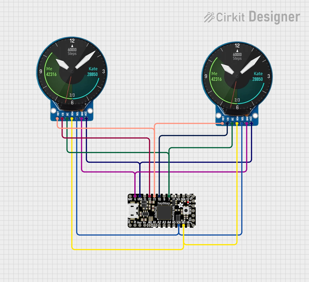
Circuit Documentation
Summary
This circuit involves two GC9A01 displays and an Adafruit ItsyBitsy M4 microcontroller. The displays are connected to the microcontroller to show graphical content. The microcontroller runs a program that controls the displays, rendering eye animations.
Component List
GC9A01 Display
- Description: A round TFT display module.
- Pins: RST, CS, DC, SDA, SCL, GND, VCC
Adafruit ItsyBitsy M4
- Description: A compact microcontroller board based on the SAMD51.
- Pins: EN, SWDIO, SWCLK, D3, D4, VBAT, GND, VBUS, D13, D12, D11, D10, D9, D7, D5_5V, SCL, SDA, TX_D1, RX_D0, D2, MISO, MOSI, SCK, A5, A4, A3, A2, A1, A0, VHI, AREF, +3V3, !RESET
Wiring Details
GC9A01 Display 1
- RST: Connected to D11 on Adafruit ItsyBitsy M4
- CS: Connected to D12 on Adafruit ItsyBitsy M4
- DC: Connected to D7 on Adafruit ItsyBitsy M4
- SDA: Connected to MOSI on Adafruit ItsyBitsy M4
- SCL: Connected to SCK on Adafruit ItsyBitsy M4
- GND: Connected to GND on Adafruit ItsyBitsy M4
- VCC: Connected to VBUS on Adafruit ItsyBitsy M4
GC9A01 Display 2
- RST: Connected to D11 on Adafruit ItsyBitsy M4
- CS: Connected to D10 on Adafruit ItsyBitsy M4
- DC: Connected to D7 on Adafruit ItsyBitsy M4
- SDA: Connected to MOSI on Adafruit ItsyBitsy M4
- SCL: Connected to SCK on Adafruit ItsyBitsy M4
- GND: Connected to GND on Adafruit ItsyBitsy M4
- VCC: Connected to VBUS on Adafruit ItsyBitsy M4
Adafruit ItsyBitsy M4
- D11: Connected to RST on both GC9A01 displays
- D12: Connected to CS on GC9A01 Display 1
- D10: Connected to CS on GC9A01 Display 2
- D7: Connected to DC on both GC9A01 displays
- MOSI: Connected to SDA on both GC9A01 displays
- SCK: Connected to SCL on both GC9A01 displays
- GND: Connected to GND on both GC9A01 displays
- VBUS: Connected to VCC on both GC9A01 displays
Code Documentation
Main Sketch (sketch.ino)
//--------------------------------------------------------------------------
// Uncanny eyes for Adafruit 1.5" OLED (product #1431) or 1.44" TFT LCD
// (#2088).  Works on PJRC Teensy 3.x and on Adafruit M0 and M4 boards
// (Feather, Metro, etc.).  This code uses features specific to these
// boards and WILL NOT work on normal Arduino or other boards!
//
// SEE FILE "config.h" FOR MOST CONFIGURATION (graphics, pins, display type,
// etc).  Probably won't need to edit THIS file unless you're doing some
// extremely custom modifications.
//
// Adafruit invests time and resources providing this open source code,
// please support Adafruit and open-source hardware by purchasing products
// from Adafruit!
//
// Written by Phil Burgess / Paint Your Dragon for Adafruit Industries.
// MIT license.  SPI FIFO insight from Paul Stoffregen's ILI9341_t3 library.
// Inspired by David Boccabella's (Marcwolf) hybrid servo/OLED eye concept.
//--------------------------------------------------------------------------

#include <SPI.h>
#include <Adafruit_GFX.h>
#ifdef ARDUINO_ARCH_SAMD
  #include <Adafruit_ZeroDMA.h>
#endif

typedef struct {        // Struct is defined before including config.h --
  int8_t  select;       // pin numbers for each eye's screen select line
  int8_t  wink;         // and wink button (or -1 if none) specified there,
  uint8_t rotation;     // also display rotation.
} eyeInfo_t;

#include "config.h"     // ****** CONFIGURATION IS DONE IN HERE ******

#if defined(_ADAFRUIT_ST7735H_) || defined(_ADAFRUIT_ST77XXH_)
  typedef Adafruit_ST7735  displayType; // Using TFT display(s)
#else
  typedef Adafruit_SSD1351 displayType; // Using OLED display(s)
#endif

// A simple state machine is used to control eye blinks/winks:
#define NOBLINK 0       // Not currently engaged in a blink
#define ENBLINK 1       // Eyelid is currently closing
#define DEBLINK 2       // Eyelid is currently opening
typedef struct {
  uint8_t  state;       // NOBLINK/ENBLINK/DEBLINK
  uint32_t duration;    // Duration of blink state (micros)
  uint32_t startTime;   // Time (micros) of last state change
  uint32_t timeOfLastBlink = 0L, timeToNextBlink = 0L;
} eyeBlink;

typedef struct {
  boolean  eyeInMotion      = false;
  int16_t  eyeOldX=512, eyeOldY=512, eyeNewX=512, eyeNewY=512;
  uint32_t eyeMoveStartTime = 0L;
  int32_t  eyeMoveDuration  = 0L;
  int16_t         eyeX, eyeY;
  uint8_t uThreshold = 128;
} eyeMove;

#define NUM_EYES (sizeof eyeInfo / sizeof eyeInfo[0]) // config.h pin list

struct {                // One-per-eye structure
  displayType *display; // -> OLED/TFT object
  eyeBlink     blink;   // Current blink/wink state
  eyeMove      move;
} eye[NUM_EYES];

#ifdef ARDUINO_ARCH_SAMD
  // SAMD boards use DMA (Teensy uses SPI FIFO instead):
  // Two single-line 128-pixel buffers (16bpp) are used for DMA.
  // Though you'd think fewer larger transfers would improve speed,
  // multi-line buffering made no appreciable difference.
  uint16_t          dmaBuf[2][128];
  uint8_t           dmaIdx = 0; // Active DMA buffer # (alternate fill/send)
  Adafruit_ZeroDMA  dma;
  DmacDescriptor   *descriptor;

  // DMA transfer-in-progress indicator and callback
  static volatile bool dma_busy = false;
  static void dma_callback(Adafruit_ZeroDMA *dma) { dma_busy = false; }
#endif

uint32_t startTime;  // For FPS indicator

// INITIALIZATION -- runs once at startup ----------------------------------

void setup(void) {
  uint8_t e; // Eye index, 0 to NUM_EYES-1

  Serial.begin(115200);
  randomSeed(analogRead(A3)); // Seed random() from floating analog input

#ifdef DISPLAY_BACKLIGHT
  // Enable backlight pin, initially off
  pinMode(DISPLAY_BACKLIGHT, OUTPUT);
  digitalWrite(DISPLAY_BACKLIGHT, LOW);
#endif

  // Initialize eye objects based on eyeInfo list in config.h:
  for(e=0; e<NUM_EYES; e++) {
    eye[e].display     = new displayType(eyeInfo[e].select, DISPLAY_DC, -1);
    eye[e].blink.state = NOBLINK;
    // If project involves only ONE eye and NO other SPI devices, its
    // select line can be permanently tied to GND and corresponding pin
    // in config.h set to -1.  Best to use it though.
    if(eyeInfo[e].select >= 0) {
      pinMode(eyeInfo[e].select, OUTPUT);
      digitalWrite(eyeInfo[e].select, HIGH); // Deselect them all
    }
    // Also set up an individual eye-wink pin if defined:
    if(eyeInfo[e].wink >= 0) pinMode(eyeInfo[e].wink, INPUT_PULLUP);
  }
#if defined(BLINK_PIN) && (BLINK_PIN >= 0)
  pinMode(BLINK_PIN, INPUT_PULLUP); // Ditto for all-eyes blink pin
#endif

#if defined(DISPLAY_RESET) && (DISPLAY_RESET >= 0)
  // Because both displays share a common reset pin, -1 is passed to
  // the display constructor above to prevent the begin() function from
  // resetting both displays after one is initialized.  Instead, handle
  // the reset manually here to take care of both displays just once:
  pinMode(DISPLAY_RESET, OUTPUT);
  digitalWrite(DISPLAY_RESET,