Arduino and Raspberry Pi Controlled Robotic System with Motion Detection and Load Sensing
Circuit Documentation
Summary
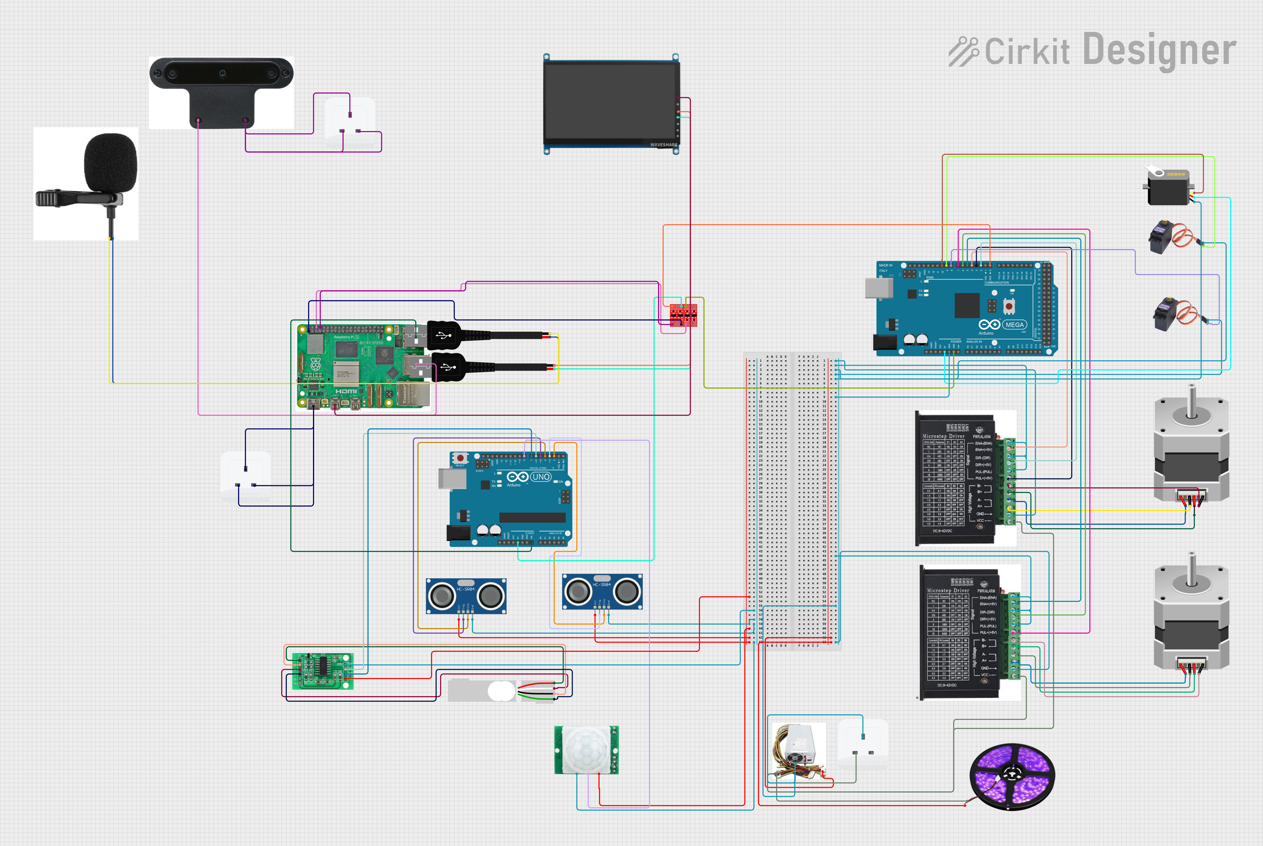
This document provides a detailed overview of a complex circuit that includes a variety of components such as microcontrollers (Arduino Mega 2560 and Arduino UNO), stepper motors with drivers, servos, sensors (HC-SR04 Ultrasonic and HC-SR501 Motion), a load cell with an HX711 interface, power supply units, LED light strips, a Raspberry Pi 5, an OAK-D camera, a WaveShare display, and USB connections. The circuit is designed to control and power motors, read sensor data, and interface with various peripherals. The microcontrollers are programmed to manage the inputs and outputs of the circuit, and the Raspberry Pi serves as a higher-level controller or processing unit.
Component List
- Arduino Mega 2560: A microcontroller board based on the ATmega2560, with a wide range of input/output options.
- Arduino UNO: A microcontroller board based on the ATmega328P, commonly used for simple control and sensing tasks.
- Stepper Motor (Bipolar): A type of electric motor that is driven by alternating current and can be precisely controlled.
- MG996R: A high-torque digital servo motor commonly used in robotics.
- Servo: A rotary actuator that allows for precise control of angular position.
- Raspberry Pi 5: A small single-board computer with a broad set of capabilities for computing tasks.
- HC-SR04 Ultrasonic Sensor: A sensor that measures distance by emitting ultrasonic waves and timing their return after bouncing off objects.
- HC-SR501 Motion sensor: A passive infrared sensor that detects motion by sensing changes in the infrared levels emitted by surrounding objects.
- Load Cell - Red/white/black/green: A transducer that converts force into an electrical signal.
- Stepper driver: A device that controls the operation of a stepper motor.
- Bi-Directional Logic Level Converter: A device that safely steps down 5V signals to 3.3V and steps up 3.3V to 5V at the same time.
- HX711 - Bridge Sensor Interface: An ADC converter that is designed for high precision electronic scale and design, with two analog input channels.
- Power Supply: Provides regulated voltage and current for the circuit.
- LED Light Strips (Violet): Strips of LEDs that emit violet light, used for illumination or signaling.
- OAK-D: An AI-powered spatial computing camera.
- 7 inch WaveShare (H): A 7-inch HDMI display with touch capability.
- USB male 2 pin connection: A USB connector used for power supply or data transfer.
- Socket: A connector that provides electrical power from the mains.
- USB microphone: A microphone that connects and draws power via USB.
Wiring Details
Arduino Mega 2560
- GND: Connected to the ground of various components including stepper drivers, servos, and power supply.
- 5V: Provides power to the servo.
- D0 RX0: Connected to the HV1 pin of the Bi-Directional Logic Level Converter.
- D2 PWM: Connected to the DIR+ pin of one stepper driver.
- D3 PWM: Connected to the PUL + pin of one stepper driver.
- D4 PWM: Connected to the ENA - pin of one stepper driver.
- D5 PWM: Connected to the ENA - pin of another stepper driver.
- D6 PWM: Connected to the DIR+ pin of another stepper driver.
- D7 PWM: Connected to the PUL + pin of another stepper driver.
- D8 PWM: Connected to the SIG pin of one MG996R servo.
- D9 PWM: Connected to the SIG pin of another MG996R servo.
- D10 PWM: Connected to the pulse pin of a servo.
Arduino UNO
- 5V: Connected to the HV pin of the Bi-Directional Logic Level Converter.
- Vin: Connected to the USB 2.0 pin of the Raspberry Pi 5.
- D8: Connected to the OUT pin of the HC-SR501 Motion sensor.
- D7: Connected to the SCK - CLOCK (IN) pin of the HX711 - Bridge Sensor Interface.
- D6: Connected to the DATA (OUT) pin of the HX711 - Bridge Sensor Interface.
- D5: Connected to the TRIG pin of one HC-SR04 Ultrasonic Sensor.
- D4: Connected to the ECHO pin of one HC-SR04 Ultrasonic Sensor.
- D3: Connected to the TRIG pin of another HC-SR04 Ultrasonic Sensor.
- D2: Connected to the ECHO pin of another HC-SR04 Ultrasonic Sensor.
Stepper Motor (Bipolar)
- Connected to the corresponding B-, B+, A-, and A+ pins of the stepper drivers.
MG996R Servo
- GND: Shared ground with other components.
- SIG: Signal pin connected to the Arduino Mega 2560.
Servo
- gnd: Shared ground with other components.
- vcc: Power from the 5V pin of the Arduino Mega 2560.
- pulse: Signal pin connected to the Arduino Mega 2560.
Raspberry Pi 5
- Type-C: Power input connected to the mains via a socket.
- Micro HDMI 1: Connected to the HDMI pin of the 7 inch WaveShare (H) display.
- USB 3.0: Connected to the USB pin of the OAK-D camera.
- GND: Shared ground with the Bi-Directional Logic Level Converter.
- 3.3v: Connected to the LV pin of the Bi-Directional Logic Level Converter.
- GPIO 14: Connected to the LV1 pin of the Bi-Directional Logic Level Converter.
HC-SR04 Ultrasonic Sensor
- VCC: Power input from the 3.3/3.5V Supply pin of the HX711 - Bridge Sensor Interface.
- GND: Shared ground with other components.
- TRIG: Trigger pin connected to the Arduino UNO.
- ECHO: Echo pin connected to the Arduino UNO.
HC-SR501 Motion sensor
- VCC: Power input from the 3.3/3.5V Supply pin of the HX711 - Bridge Sensor Interface.
- GND: Shared ground with other components.
- OUT: Output pin connected to the Arduino UNO.
Load Cell - Red/white/black/green
- Connected to the corresponding E+, A-, E-, and A+ pins of the HX711 - Bridge Sensor Interface.
Stepper driver
- ENA, DIR-, PUL-, GND: Shared ground and control signals from the Arduino Mega 2560.
- VCC: Power input from the 12V pin of the Power Supply.
- B-, B+, A-, A+: Connected to the corresponding pins of the stepper motors.
Power Supply
- 12V: Provides power to the stepper drivers and LED Light Strips.
- GND: Shared ground with other components.
LED Light Strips (Violet)
- VCC: Power input from the 12V pin of the Power Supply.
- GND: Shared ground with other components.
OAK-D
- Power: Connected to the mains via a socket.
- USB: Connected to the USB 3.0 pin of the Raspberry Pi 5.
7 inch WaveShare (H)
- HDMI: Connected to the Micro HDMI 1 pin of the Raspberry Pi 5.
- USB Power: Connected to the Positive + pin of a USB male 2 pin connection.
- -: Connected to the Negative - pin of a USB male 2 pin connection.
USB microphone
- USB power1: Connected to the Positive + pin of a USB male 2 pin connection.
- USB power2: Connected to the Negative - pin of a USB male 2 pin connection.
Documented Code
Arduino Mega 2560 Code (sketch.ino)
void setup() {
  // put your setup code here, to run once:

}

void loop() {
  // put your main code here, to run repeatedly:

}
Arduino UNO Code (sketch.ino)
void setup() {
  // put your setup code here, to run once:

}

void loop() {
  // put your main code here, to run repeatedly:

}
Note: The actual functionality of the code is not provided in the input and would typically include the initialization of pins, configuration of peripherals, and the main control loop that governs the behavior of the circuit.