
Arduino UNO Based Weather Monitoring System with LCD Display
View and Edit Project In Cirkit Designer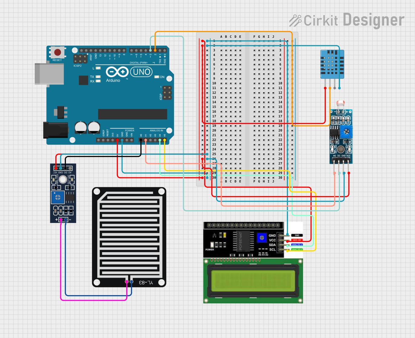
Circuit Documentation
Summary
The circuit in question is designed around an Arduino UNO microcontroller, which serves as the central processing unit. The circuit includes an LCD I2C display for output, a DHT11 humidity and temperature sensor for environmental data collection, a Module LDR for light intensity measurement, and a YL-83 rain sensor system for detecting raindrops. The Arduino UNO is responsible for interfacing with these sensors and modules, processing their signals, and displaying relevant information on the LCD.
Component List
Arduino UNO
- Microcontroller board based on the ATmega328P
- It has 14 digital input/output pins, 6 analog inputs, a 16 MHz quartz crystal, a USB connection, a power jack, an ICSP header, and a reset button.
LCD I2C Display
- An alphanumeric liquid crystal display with an I2C interface
- It allows for displaying text on the screen with less wiring complexity due to the I2C communication.
DHT11 Humidity and Temperature Sensor
- A basic, ultra-low-cost digital temperature and humidity sensor
- It uses a capacitive humidity sensor and a thermistor to measure the surrounding air and outputs a digital signal on the data pin.
Module LDR (Light Dependent Resistor)
- A sensor module that includes an LDR to measure light intensity
- It provides both analog and digital outputs; the digital output can be thresholded.
YL-83 Rain Sensor System
- Consists of a detection board and a control board
- The detection board senses the presence of raindrops, and the control board processes the signal and provides digital and analog outputs.
Wiring Details
Arduino UNO
- 5V and GND are used to power the connected components.
- A0 is connected to the digital output (DO) of the YL-83 Rain Sensor - Control Board.
- A1 is connected to the analog output (AO) of the Module LDR.
- A4 (SDA) and A5 (SCL) are used for I2C communication with the LCD I2C Display.
- D2 is connected to the data pin of the DHT11 Humidity and Temperature Sensor.
- D3 is connected to the digital output (DO) of the Module LDR.
LCD I2C Display
- VCC is connected to the 5V supply from the Arduino UNO.
- GND is connected to the ground.
- SDA and SCL are connected to the I2C data and clock lines on the Arduino UNO.
DHT11 Humidity and Temperature Sensor
- VDD is connected to the 5V supply from the Arduino UNO.
- DATA is connected to digital pin D2 on the Arduino UNO.
- GND is connected to the ground.
Module LDR
- VCC is connected to the 5V supply from the Arduino UNO.
- GND is connected to the ground.
- DO is connected to digital pin D3 on the Arduino UNO.
- AO is connected to analog pin A1 on the Arduino UNO.
YL-83 Rain Sensor - Detection Board
- POS and NEG are connected to the corresponding NEG and POS pins on the YL-83 Rain Sensor - Control Board.
YL-83 Rain Sensor - Control Board
- VCC is connected to the 5V supply from the Arduino UNO.
- GND is connected to the ground.
- DO is connected to analog pin A0 on the Arduino UNO.
- The POS and NEG pins are connected to the corresponding NEG and POS pins on the YL-83 Rain Sensor - Detection Board.
Documented Code
Arduino UNO Code (sketch.ino)
void setup() {
  // put your setup code here, to run once:

}

void loop() {
  // put your main code here, to run repeatedly:

}
This code template provides the basic structure for an Arduino sketch, with setup() function to initialize settings and loop() function to contain the main logic that will run continuously. The actual implementation details will depend on the specific requirements of the circuit's functionality.