
Circuit Documentation
Summary of the Circuit
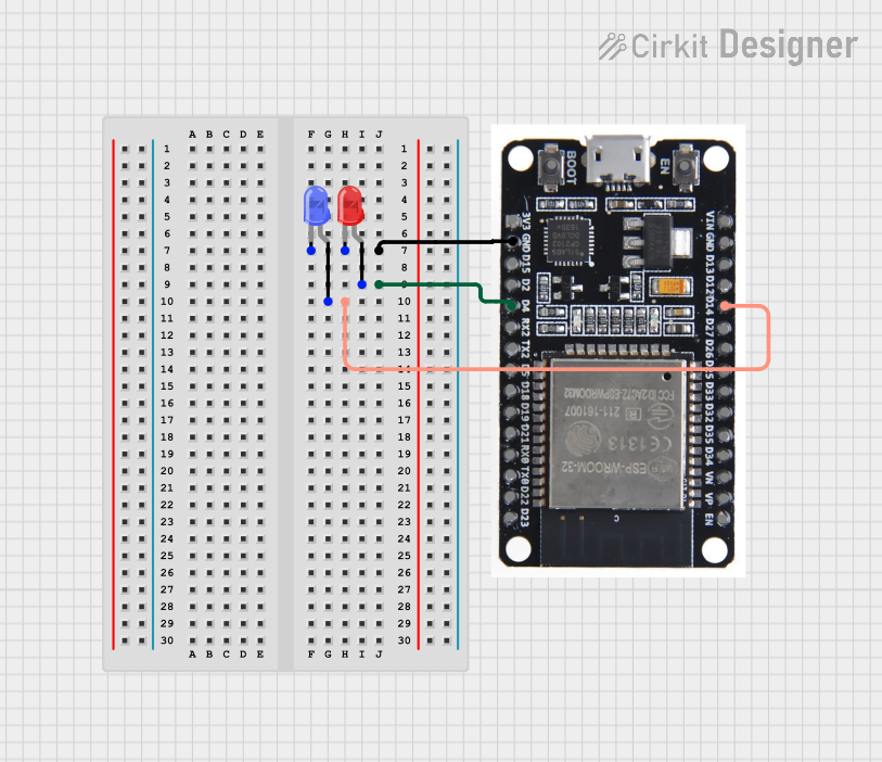
This circuit consists of an ESP32 microcontroller that is used to control two LEDs: one red and one blue. The ESP32 has several GPIO pins, of which two are used to control the LEDs. The red LED is connected to pin D4, and the blue LED is connected to pin D14. Both LEDs share a common ground connection with the ESP32. The microcontroller runs a program that blinks the red LED with a delay of 5 seconds between turning on and off. The code for the blue LED is not provided, but it is assumed to be similar to the red LED's code.
Component List
ESP32 Microcontroller
- Description: A microcontroller with Wi-Fi and Bluetooth capabilities, featuring a wide range of GPIO pins.
- Purpose: Acts as the central processing unit of the circuit, controlling the LEDs' blinking behavior.
LED: Two Pin (red)
- Description: A basic red LED with an anode and cathode for simple light-emitting applications.
- Purpose: To provide a visual indication, blinking as per the control signals from the ESP32.
LED: Two Pin (blue)
- Description: A basic blue LED with an anode and cathode, similar to the red LED but emitting blue light.
- Purpose: To provide a visual indication, presumably blinking as per control signals from the ESP32 (code not provided).
Wiring Details
ESP32 Microcontroller
- GND: Connected to the cathodes of both the red and blue LEDs.
- D4: Connected to the anode of the red LED.
- D14: Connected to the anode of the blue LED.
LED: Two Pin (red)
- Cathode: Connected to the GND pin on the ESP32.
- Anode: Connected to pin D4 on the ESP32.
LED: Two Pin (blue)
- Cathode: Connected to the GND pin on the ESP32.
- Anode: Connected to pin D14 on the ESP32.
Documented Code
Code for the Red LED on ESP32
/*
 * This Arduino Sketch controls an LED connected to an ESP32 microcontroller.
 * The LED is connected to pin D4 and GND. The LED will blink with a delay of
 * 5000 ms (5 seconds) between turning on and off.
 */

void setup() {
  // Initialize the digital pin D4 as an output.
  pinMode(4, OUTPUT);
}

void loop() {
  // Turn the LED on (HIGH is the voltage level)
  digitalWrite(4, HIGH);
  // Wait for 5000 milliseconds (5 seconds)
  delay(5000);
  // Turn the LED off by making the voltage LOW
  digitalWrite(4, LOW);
  // Wait for 5000 milliseconds (5 seconds)
  delay(5000);
}
Note: The code for the blue LED is not provided, but it is expected to be similar to the red LED's code, with the appropriate pin number (D14) used in place of D4.