Arduino-Based Smart Lock System with IR and Ultrasonic Sensors
Circuit Documentation
Summary
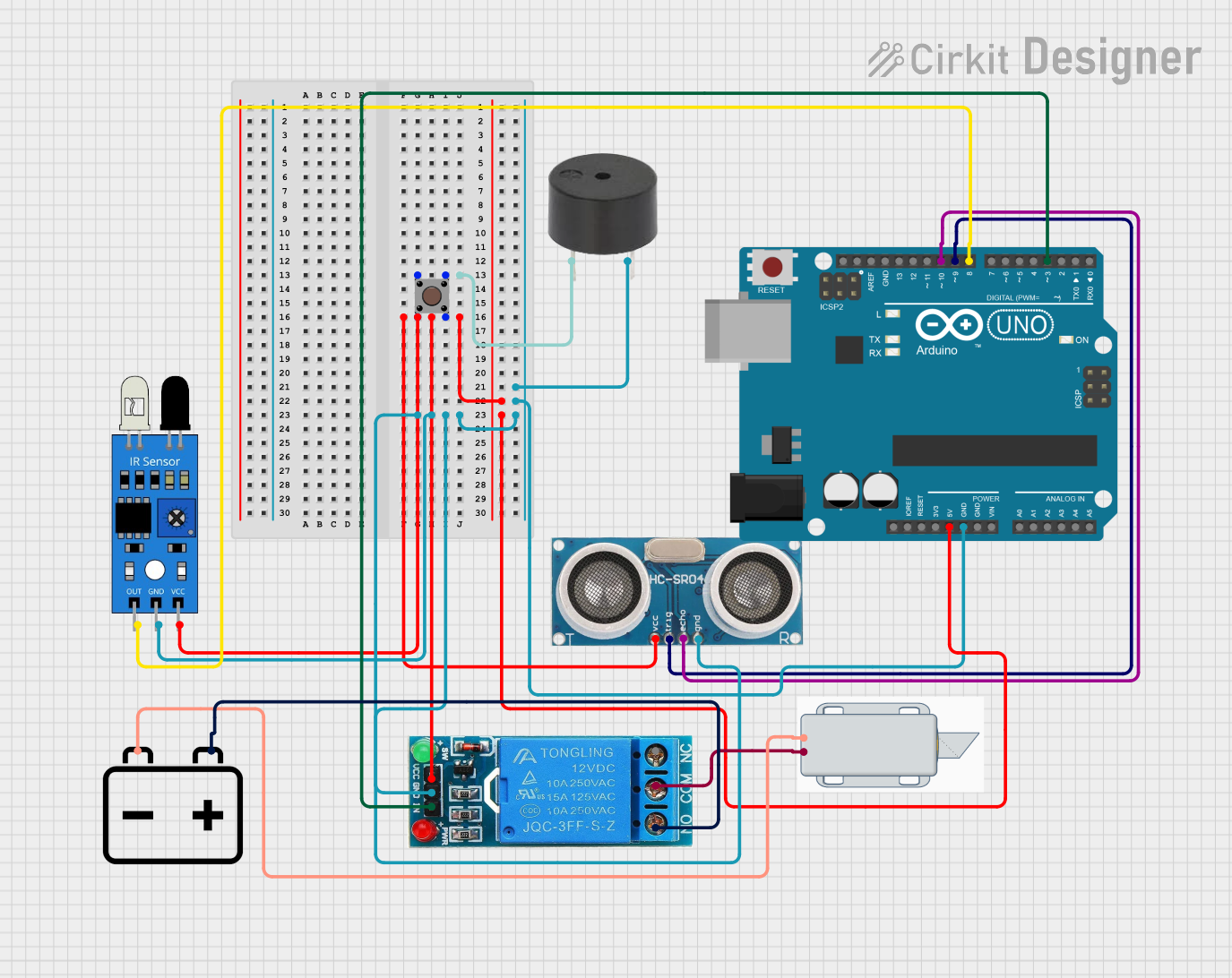
This circuit integrates various sensors and actuators with an Arduino UNO microcontroller to create a functional system. The components include an IR sensor, an ultrasonic sensor, a buzzer, a 12V battery, a 12V solenoid lock, a 12V single-channel relay, and a pushbutton. The Arduino UNO serves as the central controller, interfacing with the sensors and actuators to perform specific tasks.
Component List
IR Sensor
- Pins: out, gnd, vcc
- Description: Infrared sensor used for detecting objects or obstacles.
- Purpose in Circuit: Provides object detection capability.
Ultrasonic Sensor
- Pins: +VCC, Trigger, Echo, GND
- Description: Ultrasonic sensor used for distance measurement.
- Purpose in Circuit: Measures the distance to an object.
Buzzer
- Pins: PIN, GND
- Description: Audio signaling device.
- Purpose in Circuit: Provides audible alerts.
12V Battery
- Pins: -, +
- Description: Power source for the circuit.
- Purpose in Circuit: Supplies 12V power to the components.
Arduino UNO
- Pins: UNUSED, IOREF, Reset, 3.3V, 5V, GND, Vin, A0, A1, A2, A3, A4, A5, SCL, SDA, AREF, D13, D12, D11, D10, D9, D8, D7, D6, D5, D4, D3, D2, D1, D0
- Description: Microcontroller board based on the ATmega328P.
- Purpose in Circuit: Central controller for the circuit.
12V Solenoid Lock
- Pins: -, +
- Description: Electromechanical lock.
- Purpose in Circuit: Provides locking mechanism.
12V Single Channel Relay
- Pins: NC, COM, NO, IN, GND, VCC
- Description: Relay module for switching high-power devices.
- Purpose in Circuit: Controls the solenoid lock.
Pushbutton
- Pins: Pin 3 (out), Pin 4 (out), Pin 1 (in), Pin 2 (in)
- Description: Momentary pushbutton switch.
- Purpose in Circuit: User input for triggering actions.
Wiring Details
IR Sensor
- out connected to D8 on Arduino UNO
- gnd connected to GND on Arduino UNO
- vcc connected to 5V on Arduino UNO
Ultrasonic Sensor
- +VCC connected to 5V on Arduino UNO
- Trigger connected to D9 on Arduino UNO
- Echo connected to D10 on Arduino UNO
- GND connected to GND on Arduino UNO
Buzzer
- PIN connected to Pin 3 (out) on Pushbutton
- GND connected to GND on Arduino UNO
12V Battery
- - connected to - on 12V Solenoid Lock
- + connected to NO on 12V Single Channel Relay
Arduino UNO
- 5V connected to vcc on IR Sensor, +VCC on Ultrasonic Sensor, VCC on 12V Single Channel Relay
- GND connected to gnd on IR Sensor, GND on Ultrasonic Sensor, GND on Buzzer, GND on 12V Single Channel Relay
- D8 connected to out on IR Sensor
- D9 connected to Trigger on Ultrasonic Sensor
- D10 connected to Echo on Ultrasonic Sensor
- D3 connected to IN on 12V Single Channel Relay
12V Solenoid Lock
- - connected to - on 12V Battery
- + connected to COM on 12V Single Channel Relay
12V Single Channel Relay
- NC not connected
- COM connected to + on 12V Solenoid Lock
- NO connected to + on 12V Battery
- IN connected to D3 on Arduino UNO
- GND connected to GND on Arduino UNO
- VCC connected to 5V on Arduino UNO
Pushbutton
- Pin 3 (out) connected to PIN on Buzzer
- Pin 4 (out) connected to VCC on 12V Single Channel Relay, vcc on IR Sensor, +VCC on Ultrasonic Sensor, 5V on Arduino UNO
- Pin 1 (in) connected to Pin 3 (out)
- Pin 2 (in) connected to Pin 4 (out)
Code Documentation
Arduino UNO Code
void setup() {
  // put your setup code here, to run once:

}

void loop() {
  // put your main code here, to run repeatedly:

}
This code is a basic template for the Arduino UNO. The setup() function is where you initialize your components and settings, and the loop() function is where the main logic of your program runs repeatedly.
Additional Documentation
The additional documentation file is empty and can be used to add further details or instructions as needed.