
Arduino UNO Based Piezo Sensor Array with LED Indicators and I2C LCD Display
View and Edit Project In Cirkit Designer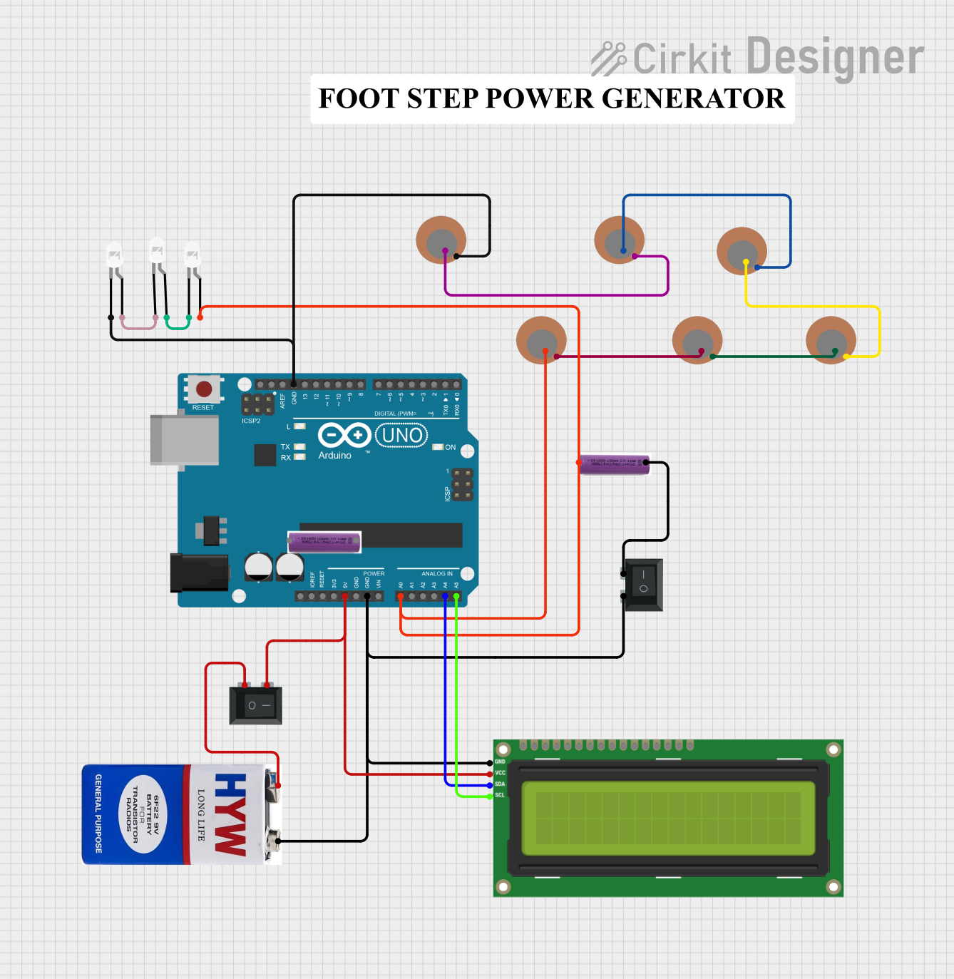
Circuit Documentation
Summary of the Circuit
This circuit is designed around an Arduino UNO microcontroller, which serves as the central processing unit. The circuit includes a variety of components such as Piezo Sensors, LEDs, an I2C LCD 16x2 Screen, batteries, and Rocker Switches (SPST). The Arduino UNO is responsible for interfacing with the Piezo Sensors and controlling the LEDs based on the sensor inputs. The I2C LCD screen is used to display information, and the Rocker Switches are used to control power to the circuit. The batteries provide the necessary power to the components.
Component List
Microcontroller
- Arduino UNO: A microcontroller board based on the ATmega328P, with a variety of digital and analog I/O pins.
Sensors
- Piezo Sensors: These are used to detect vibrations or pressure changes. There are multiple Piezo Sensors in the circuit.
Indicators
- LEDs (white): Light Emitting Diodes used as visual indicators.
Display
- I2C LCD 16x2 Screen: A 16x2 character LCD display that uses the I2C communication protocol.
Power Sources
- 3.7v batteries: Provide power to the circuit.
- 9V battery: Provides power to the circuit.
Switches
- Rocker Switches (SPST): Single Pole Single Throw switches used to control the power flow in the circuit.
Wiring Details
Arduino UNO
- 5V & GND: Connected to the I2C LCD screen and Rocker Switches for power distribution.
- A0: Connected to a Piezo Sensor and an LED.
- A4 (SDA): Connected to the SDA pin of the I2C LCD screen for data communication.
- A5 (SCL): Connected to the SCL pin of the I2C LCD screen for clock signal.
Piezo Sensors
- + & -: Interconnected with each other in a chain and also connected to the Arduino UNO and LEDs.
LEDs (white)
- Anode & Cathode: Connected to the Piezo Sensors and Arduino UNO. Some LEDs are connected in series.
I2C LCD 16x2 Screen
- VCC (5V) & GND: Powered by the Arduino UNO through a Rocker Switch.
- SDA & SCL: Connected to the corresponding SDA and SCL pins on the Arduino UNO for I2C communication.
Rocker Switches (SPST)
- Pins 1 & 2: Used to control the power from the batteries to the Arduino UNO and the I2C LCD screen.
Batteries
- + & -: Provide power to the circuit through the Rocker Switches.
Documented Code
Arduino UNO Code (sketch.ino)
void setup() {
  // put your setup code here, to run once:

}

void loop() {
  // put your main code here, to run repeatedly:

}
Additional Notes
- The code provided for the Arduino UNO is a template with empty
setup()andloop()functions. The actual implementation should include the initialization of the I2C communication for the LCD screen, reading inputs from the Piezo Sensors, and controlling the LEDs based on the sensor inputs. - There is an additional empty text file named "documentation.txt" which is intended for further documentation purposes.