
Arduino-Controlled Line Following Robot with Dual IR Sensors
View and Edit Project In Cirkit Designer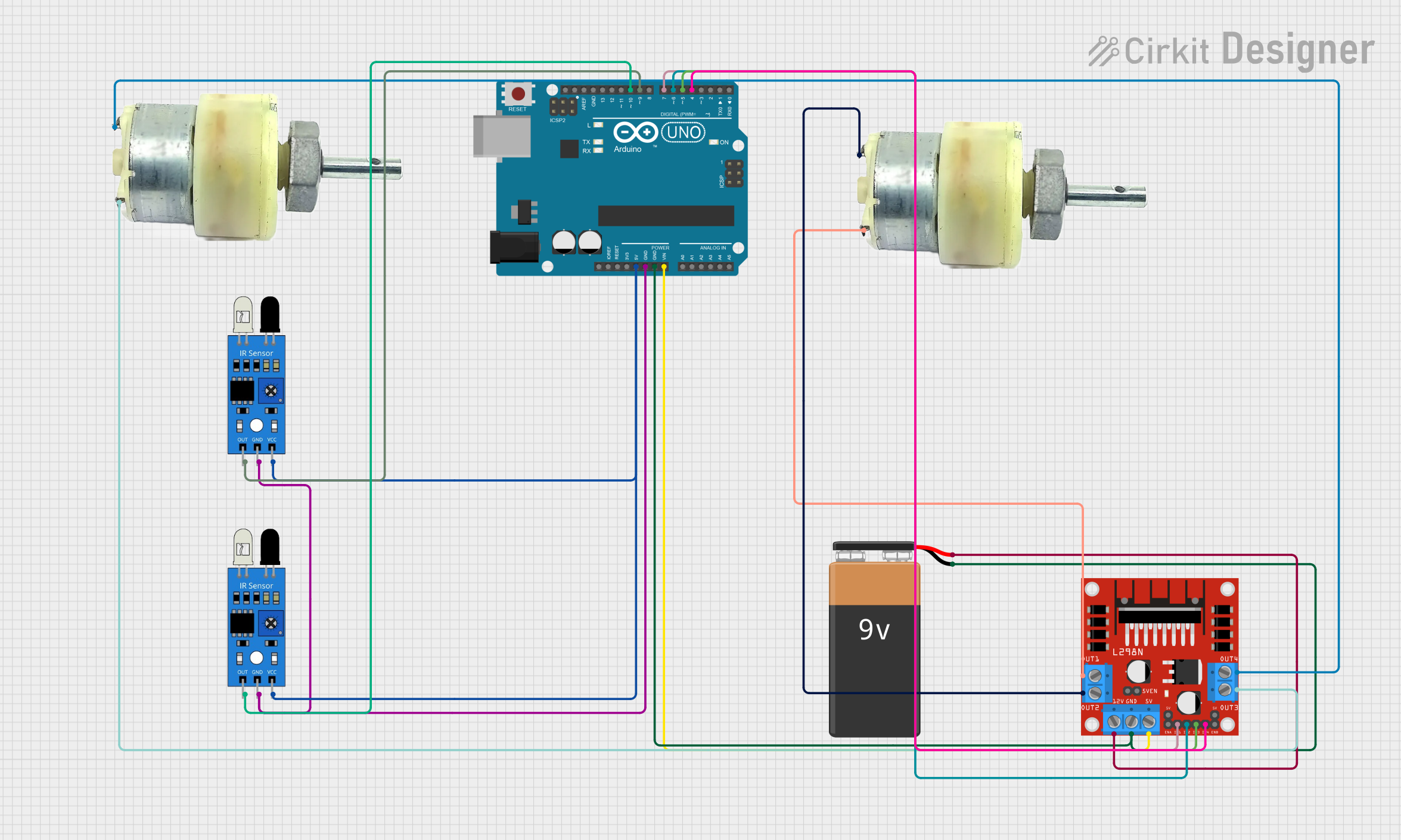
Circuit Documentation
Summary
This circuit is designed to control a pair of 12V geared motors using an Arduino UNO and an L298N DC motor driver. The motors are intended to be driven based on the input from two infrared (IR) sensors. The Arduino UNO is powered by a 9V battery and also provides power to the IR sensors. The L298N motor driver interfaces with the Arduino to control the direction and speed of the motors based on the sensor inputs. The circuit is likely part of a robotic system where the IR sensors are used for navigation, such as avoiding obstacles or following a path.
Component List
Arduino UNO
- Microcontroller board based on the ATmega328P
- Provides I/O pins for interfacing with sensors, motor drivers, and other peripherals
- Can be powered via USB or external power sources like batteries
9V Battery
- Provides power to the Arduino UNO and the motor driver
- Typically used for portable power supply in small electronics
12V Geared Motors (x2)
- Electric motors with a gearbox to provide high torque at lower speeds
- Typically used in robotics and automation for driving wheels or other mechanical parts
IR Sensors (x2)
- Sensors that detect proximity or the presence of objects using infrared light
- Commonly used in obstacle detection, line following, and other robotic applications
L298N DC Motor Driver
- A module capable of driving two DC motors with direction and speed control
- Accepts logic-level inputs from a microcontroller to control the motors
Wiring Details
Arduino UNO
5Vpin provides power to both IR sensorsGNDpin is connected to the ground pins of the IR sensors and the GND of the L298N motor driverVinpin is connected to the5Vinput of the L298N motor driver to power it- Digital pins
D10andD9are connected to the output pins of the left and right IR sensors, respectively - Digital pins
D7,D6,D5, andD4are connected to theIN1,IN2,IN3, andIN4inputs of the L298N motor driver to control the motors
9V Battery
+terminal is connected to the12Vinput of the L298N motor driver to power the motors-terminal is connected to the GND of the Arduino UNO and the L298N motor driver
12V Geared Motors
- The terminals of each motor are connected to the
OUT1,OUT2,OUT3, andOUT4outputs of the L298N motor driver
IR Sensors
vccpins are connected to the5Voutput of the Arduino UNOgndpins are connected to the GND of the Arduino UNOoutpins are connected to theD10andD9pins of the Arduino UNO for signal reading
L298N DC Motor Driver
12Vinput is connected to the+terminal of the 9V batteryGNDis connected to the-terminal of the 9V battery and the GND of the Arduino UNO5Vinput is connected to theVinof the Arduino UNOIN1,IN2,IN3, andIN4inputs are connected to theD7,D6,D5, andD4pins of the Arduino UNOOUT1,OUT2,OUT3, andOUT4outputs are connected to the terminals of the 12V geared motors
Documented Code
#define LS 10      // left sensor
#define RS 9       // right sensor
#define LM1 7      // motor Driver in1
#define LM2 6      // motor Driver in2
#define RM1 5      // motor Driver in3
#define RM2 4      // motor Driver in4

void setup()
{
  pinMode(LS, INPUT);  // Set left sensor as input
  pinMode(RS, INPUT);  // Set right sensor as input
  pinMode(LM1, OUTPUT); // Set motor driver inputs as outputs
  pinMode(LM2, OUTPUT);
  pinMode(RM1, OUTPUT);
  pinMode(RM2, OUTPUT);
}

void loop()
{
  // Read sensor values and control motor driver outputs accordingly
  if(!digitalRead(LS) && !digitalRead(RS))
  {
    // Move forward
    digitalWrite(LM1, HIGH);
    digitalWrite(LM2, LOW);
    digitalWrite(RM1, HIGH);
    digitalWrite(RM2, LOW);
  }

  if(digitalRead(LS) && !digitalRead(RS))
  {
    // Turn left
    digitalWrite(LM1, LOW);
    digitalWrite(LM2, LOW);
    digitalWrite(RM1, HIGH);
    digitalWrite(RM2, LOW);
  }

  if(!digitalRead(LS) && digitalRead(RS))
  {
    // Turn right
    digitalWrite(LM1, HIGH);
    digitalWrite(LM2, LOW);
    digitalWrite(RM1, LOW);
    digitalWrite(RM2, LOW);
  }

  if(digitalRead(LS) && digitalRead(RS))
  {
    // Stop
    digitalWrite(LM1, LOW);
    digitalWrite(LM2, LOW);
    digitalWrite(RM1, LOW);
    digitalWrite(RM2, LOW);
  }
}
This code is designed to read inputs from two IR sensors and control the motors through the L298N motor driver. The LS and RS constants represent the left and right sensors, respectively, while LM1, LM2, RM1, and RM2 represent the motor driver inputs. The setup function initializes the sensor pins as inputs and the motor driver pins as outputs. The loop function continuously reads the sensor inputs and controls the motor outputs to move forward, turn left, turn right, or stop based on the sensor readings.