
ESP32-Based Current Monitoring System with LCD Display and Relay Control
View and Edit Project In Cirkit Designer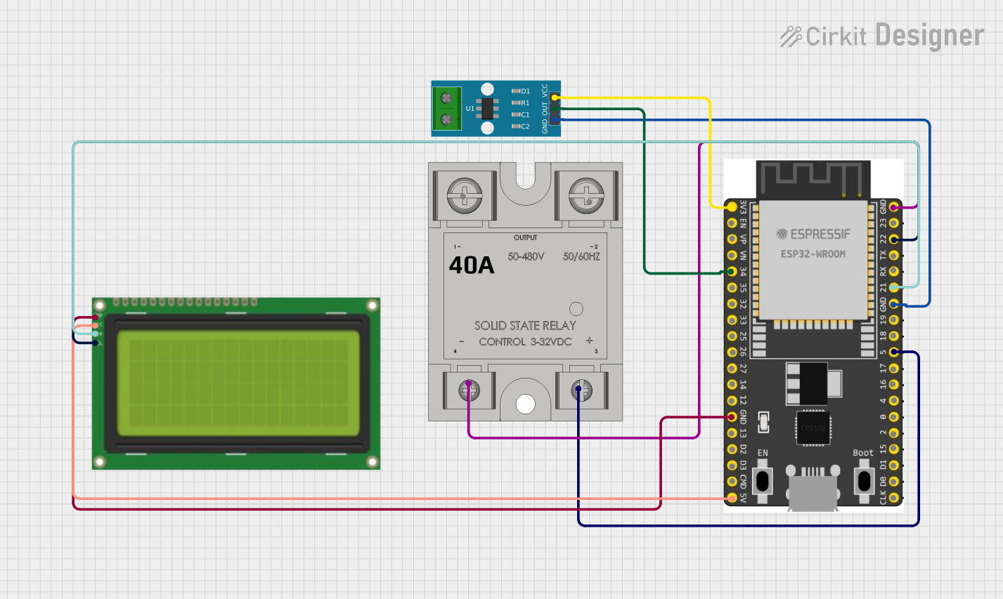
Circuit Documentation
Summary
This circuit is designed to monitor the current using an ACS712 current sensor and display the readings on a 20x4 I2C LCD. Additionally, it controls a solid-state relay (SSR-40A) based on the current readings. The ESP32 Wroom Dev Kit is used as the microcontroller to interface with the current sensor, LCD, and relay.
Component List
ESP32 Wroom Dev Kit
- Description: A powerful microcontroller with Wi-Fi and Bluetooth capabilities.
- Pins: 3V3, EN, VP, VN, GPIO 34, GPIO 35, GPIO 32, GPIO 33, GPIO 25, GPIO 26, GPIO 27, GPIO 14, GND, GPIO 13, SD2, SD3, CMD, V5, GPIO 23, GPIO 22, TXD, RXD, GPIO 21, GPIO 19, GPIO 18, GPIO 5, GPIO 17, GPIO 16, GPIO 4, GPIO 0, GPIO 2, GPIO 15, SD1, SD0, CLK
SSR-40A
- Description: A solid-state relay used to control high-power devices.
- Pins: -, +, Lin, Lout
Lcd 20x4 I2C
- Description: A 20x4 character LCD with I2C interface.
- Pins: GND, 5V, SCA, SCL
ACS712 Current Sensor 5A 20A 30A
- Description: A current sensor capable of measuring up to 30A.
- Pins: 1, 2, GND, OUT, VCC
Wiring Details
ESP32 Wroom Dev Kit
- 3V3 connected to VCC of ACS712 Current Sensor
- GPIO 34 connected to OUT of ACS712 Current Sensor
- GND connected to GND of Lcd 20x4 I2C
- V5 connected to 5V of Lcd 20x4 I2C
- GND connected to GND of SSR-40A
- GPIO 22 connected to SCL of Lcd 20x4 I2C
- GPIO 21 connected to SCA of Lcd 20x4 I2C
- GND connected to GND of ACS712 Current Sensor
- GPIO 5 connected to + of SSR-40A
SSR-40A
- - connected to GND of ESP32 Wroom Dev Kit
- + connected to GPIO 5 of ESP32 Wroom Dev Kit
Lcd 20x4 I2C
- GND connected to GND of ESP32 Wroom Dev Kit
- 5V connected to V5 of ESP32 Wroom Dev Kit
- SCL connected to GPIO 22 of ESP32 Wroom Dev Kit
- SCA connected to GPIO 21 of ESP32 Wroom Dev Kit
ACS712 Current Sensor 5A 20A 30A
- VCC connected to 3V3 of ESP32 Wroom Dev Kit
- OUT connected to GPIO 34 of ESP32 Wroom Dev Kit
- GND connected to GND of ESP32 Wroom Dev Kit
Code Documentation
#include <Wire.h>
#include <LiquidCrystal_I2C.h>
#include <ACS712.h>

#define RELAY_PIN 5
#define CURRENT_SENSOR_PIN 34
#define CURRENT_THRESHOLD 13.0

ACS712 currentSensor(ACS712_30A, CURRENT_SENSOR_PIN);
LiquidCrystal_I2C lcd(0x27, 20, 4);

void setup() {
  pinMode(RELAY_PIN, OUTPUT);
  digitalWrite(RELAY_PIN, LOW); // Initially turn off the relay

  lcd.begin();
  lcd.backlight();
  lcd.setCursor(0, 0);
  lcd.print("Current Monitor");

  currentSensor.calibrate();
}

void loop() {
  float current = currentSensor.getCurrentAC();

  lcd.setCursor(0, 1);
  lcd.print("Current: ");
  lcd.print(current);
  lcd.print(" A");

  if (current > CURRENT_THRESHOLD) {
    digitalWrite(RELAY_PIN, LOW); // Turn off the relay
    lcd.setCursor(0, 2);
    lcd.print("Relay: OFF");
  } else {
    digitalWrite(RELAY_PIN, HIGH); // Turn on the relay
    lcd.setCursor(0, 2);
    lcd.print("Relay: ON ");
  }

  delay(1000); // Update every second
}
This code initializes the current sensor and LCD, and continuously monitors the current. If the current exceeds the threshold, the relay is turned off; otherwise, it is turned on. The current readings and relay status are displayed on the LCD.