
Arduino Pro Mini FM Radio with LCD Display and Battery Power
View and Edit Project In Cirkit Designer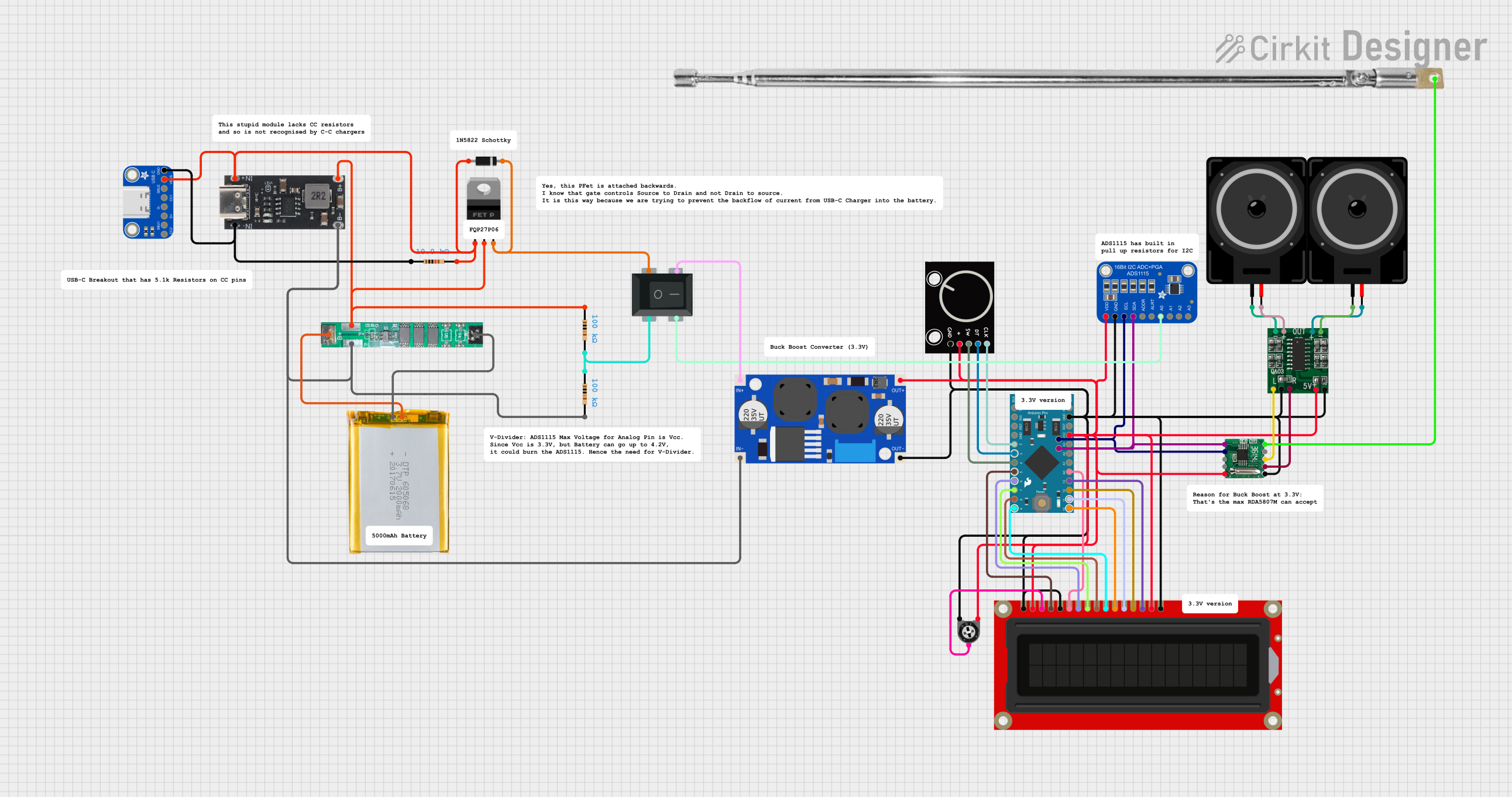
Circuit Documentation
Summary
This document provides a detailed overview of a circuit that includes various components such as an Arduino Pro Mini, an RDA5807M FM receiver, an Adafruit ADS1115 ADC, an LCD screen, a PAM8403 amplifier, a rotary encoder, a telescopic antenna, and other supporting components. The circuit is designed to interface these components to achieve a specific functionality, which is controlled by the Arduino Pro Mini microcontroller.
Component List
RDA5807M
- Description: FM receiver module
- Pins: SDA, SCL, NC, Vcc, GND, Rout, Lout, ANT
Arduino Pro Mini v13
- Description: Microcontroller board
- Pins: DTR, D0/TX, D1/RX, VCC, GND, A4, A5, RAW, RESET, A3, A2, A1, A0, D13/SCK, D12/MISO, D11 PWM/MOSI, D10 PWM/SS, D9 PWM, D8, D7, D6 PWM, D5 PWM, D4, D3 PWM, D2
Adafruit ADS1115 16Bit I2C ADC
- Description: 16-bit analog-to-digital converter
- Pins: VDD, GND, SCL, SDA, ADDR, ALERT, AIN0, AIN1, AIN2, AIN3
LCD Screen
- Description: Display module
- Pins: Backlight (GND), VSS, VDD, Contrast, RS, E, R/W, D0, D1, D2, D3, D4, D5, D6, D7, Backlight_PWR
PAM8403
- Description: Audio amplifier module
- Pins: 5vIN+, GND/IN-, R-INPUT, GND, L-INPUT, L-, L+, R+, R-
XL6009E1 Boost Converter
- Description: DC-DC boost converter
- Pins: IN+, IN-, OUT-, OUT+
Rotary Encoder
- Description: Rotary encoder for user input
- Pins: GND, +, SW, DT, CLK
Telescopic Antenna
- Description: Antenna for FM receiver
- Pins: Antenna
Loudspeaker
- Description: Audio output device
- Pins: pin1, pin2
Trimmer Potentiometer
- Description: Adjustable resistor
- Pins: leg1, wiper, leg2
- Properties: Resistance: 10000 Ohms
Rocker Switch 4 Pin
- Description: Switch for user input
- Pins: 1, 3, 2, 4
IP2312
- Description: Power management IC
- Pins: B-, B+, IN-, IN+
BMS 1S1P 3.7V 3A (for 18650)
- Description: Battery management system
- Pins: B+, P+, P-, B-
pMOS Transistor (MOSFET)
- Description: Transistor for switching
- Pins: gate, drain, source
Diode
- Description: Diode for current direction control
- Pins: cathode, anode
Resistor
- Description: Fixed resistor
- Pins: pin1, pin2
- Properties: Resistance: 10000 Ohms, 100000 Ohms
Adafruit USB Type C Breakout
- Description: USB Type-C breakout board
- Pins: GND, VBUS, SBU2, CC1, D-, D+, SBU1, CC2
2000mAh Battery
- Description: Rechargeable battery
- Pins: VCC, GND
Wiring Details
RDA5807M
- SDA: Connected to Arduino Pro Mini A4 and Adafruit ADS1115 SDA
- SCL: Connected to Arduino Pro Mini A5 and Adafruit ADS1115 SCL
- Vcc: Connected to XL6009E1 Boost Converter OUT+
- GND: Connected to XL6009E1 Boost Converter OUT-
- Rout: Connected to PAM8403 R-INPUT
- Lout: Connected to PAM8403 L-INPUT
- ANT: Connected to Telescopic Antenna Antenna
Arduino Pro Mini v13
- A4: Connected to RDA5807M SDA and Adafruit ADS1115 SDA
- A5: Connected to RDA5807M SCL and Adafruit ADS1115 SCL
- VCC: Connected to XL6009E1 Boost Converter OUT+
- GND: Connected to XL6009E1 Boost Converter OUT-
- A0: Connected to LCD screen E
- D13/SCK: Connected to LCD screen D7
- D12/MISO: Connected to LCD screen D6
- D11 PWM/MOSI: Connected to LCD screen D5
- D10 PWM/SS: Connected to LCD screen D4
- D9 PWM: Connected to LCD screen D3
- D8: Connected to LCD screen D2
- D7: Connected to LCD screen D1
- D6 PWM: Connected to LCD screen D0
- D5 PWM: Connected to LCD screen RS
- D4: Connected to Rotary Encoder SW
- D3 PWM: Connected to Rotary Encoder DT
- D2: Connected to Rotary Encoder CLK
Adafruit ADS1115 16Bit I2C ADC
- SDA: Connected to Arduino Pro Mini A4 and RDA5807M SDA
- SCL: Connected to Arduino Pro Mini A5 and RDA5807M SCL
- VDD: Connected to XL6009E1 Boost Converter OUT+
- GND: Connected to XL6009E1 Boost Converter OUT-
- AIN0: Connected to Rocker Switch 4 Pin 4
LCD Screen
- Backlight_PWR: Connected to XL6009E1 Boost Converter OUT+
- VDD: Connected to XL6009E1 Boost Converter OUT+
- Backlight (GND): Connected to XL6009E1 Boost Converter OUT-
- VSS: Connected to XL6009E1 Boost Converter OUT-
- R/W: Connected to XL6009E1 Boost Converter OUT-
- Contrast: Connected to Trimmer Potentiometer wiper
- E: Connected to Arduino Pro Mini A0
- RS: Connected to Arduino Pro Mini D5 PWM
- D7: Connected to Arduino Pro Mini D13/SCK
- D6: Connected to Arduino Pro Mini D12/MISO
- D5: Connected to Arduino Pro Mini D11 PWM/MOSI
- D4: Connected to Arduino Pro Mini D10 PWM/SS
- D3: Connected to Arduino Pro Mini D9 PWM
- D2: Connected to Arduino Pro Mini D8
- D1: Connected to Arduino Pro Mini D7
- D0: Connected to Arduino Pro Mini D6 PWM
PAM8403
- 5vIN+: Connected to XL6009E1 Boost Converter OUT+
- GND/IN-: Connected to XL6009E1 Boost Converter OUT-
- R-INPUT: Connected to RDA5807M Rout
- L-INPUT: Connected to RDA5807M Lout
- L-: Connected to Loudspeaker pin1
- L+: Connected to Loudspeaker pin2
- R+: Connected to Loudspeaker pin2
- R-: Connected to Loudspeaker pin1
XL6009E1 Boost Converter
- IN+: Connected to Rocker Switch 4 Pin 3
- IN-: Connected to BMS 1S1P 3.7V 3A P- and IP2312 B-
- OUT+: Connected to Adafruit ADS1115 VDD, Arduino Pro Mini VCC, Trimmer Potentiometer leg1, RDA5807M Vcc, LCD screen Backlight_PWR, LCD screen VDD, PAM8403 5vIN+, Rotary Encoder +
- OUT-: Connected to Adafruit ADS1115 GND, Arduino Pro Mini GND, Trimmer Potentiometer leg2, RDA5807M GND, LCD screen Backlight (GND), LCD screen VSS, LCD screen R/W, PAM8403 GND/IN-, PAM8403 GND, Rotary Encoder GND
Rotary Encoder
- GND: Connected to XL6009E1 Boost Converter OUT-
- +: Connected to XL6009E1 Boost Converter OUT+
- SW: Connected to Arduino Pro Mini D4
- DT: Connected to Arduino Pro Mini D3 PWM
- CLK: Connected to Arduino Pro Mini D2
Telescopic Antenna
- Antenna: Connected to RDA5807M ANT
Loudspeaker
- pin1: Connected to PAM8403 L- and R-
- pin2: Connected to PAM8403 L+ and R+
Trimmer Potentiometer
- leg1: