
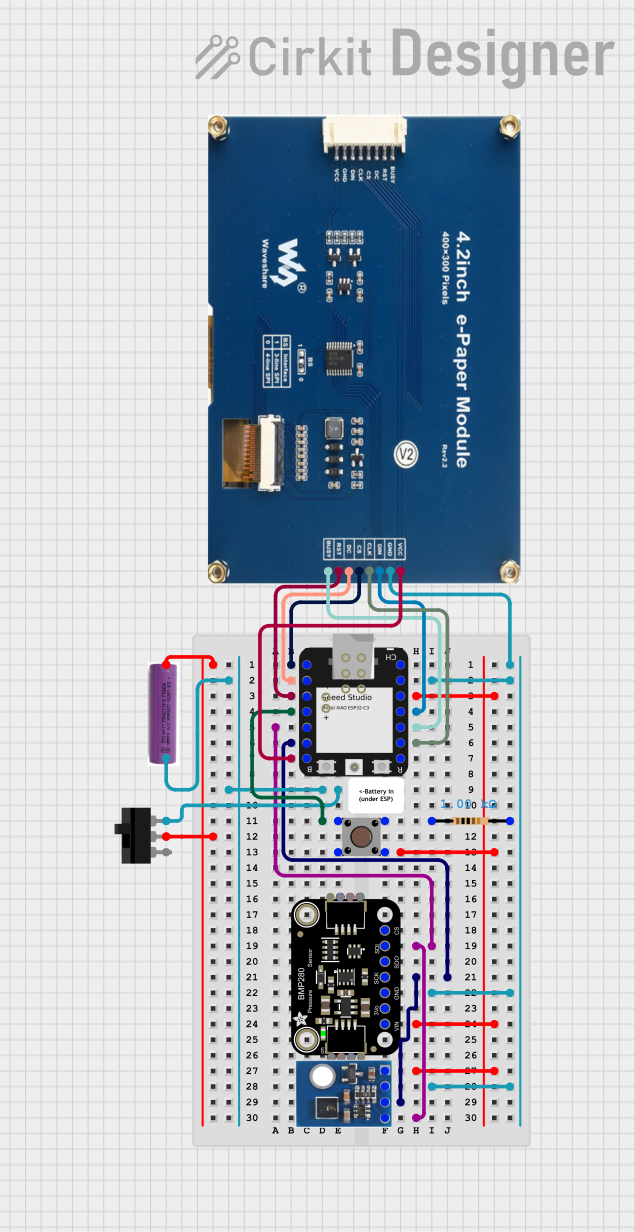
Circuit Documentation
Summary
This document provides a detailed overview of a weather station circuit powered by an ESP32-C3 microcontroller. The circuit includes various components such as sensors, a display module, a pushbutton, a toggle switch, and a battery. The ESP32-C3 microcontroller is programmed to read data from the sensors and display it on an E-Ink display. The circuit is designed to be low-power and is suitable for battery-operated applications.
Component List
ESP32-C3
- Description: A low-power microcontroller with built-in Wi-Fi and Bluetooth capabilities.
- Pins: GPIO2 / A0, GPIO3 / A1, GPIO4 / A2, GPIO5 / A3, GPIO6 / SDA, GPIO7 / SCL, GPIO21 / TX, GPIO20 / RX, GPIO8 / SCK, GPIO9 / MISO, GPIO10 / MOSI, 3.3V, GND, 5V
Pushbutton
- Description: A simple pushbutton used for user input.
- Pins: Pin 3 (out), Pin 4 (out), Pin 1 (in), Pin 2 (in)
Resistor
- Description: A 1000 Ohm resistor used for current limiting.
- Pins: pin1, pin2
- Properties: Resistance: 1000 Ohms
3.7V Battery
- Description: A battery used to power the circuit.
- Pins: +, -
Toggle Switch
- Description: A switch used to control the power from the battery.
- Pins: L1, COM, L2
Adafruit BMP280
- Description: A barometric pressure and temperature sensor.
- Pins: VCC, 3.3V, GND, SCK/SCL, SDO/ADR, SDI/SDA, CS
AHT21
- Description: A temperature and humidity sensor.
- Pins: Vin, GND, SCL, SDI
4.2in 400x600 E-Ink Paper Display Module
- Description: An E-Ink display module used to display sensor data.
- Pins: Vcc, GND, DIN, CLK, CS, DC, RST, BUSY
Wiring Details
ESP32-C3
- GPIO2 / A0: Connected to CS of the E-Ink Display Module
- GPIO3 / A1: Connected to DC of the E-Ink Display Module
- GPIO4 / A2: Connected to RST of the E-Ink Display Module
- GPIO5 / A3: Connected to Pin 2 (in) of the Pushbutton
- GPIO6 / SDA: Connected to SDI/SDA of the BMP280 and SDI of the AHT21
- GPIO7 / SCL: Connected to SCK/SCL of the BMP280 and SCL of the AHT21
- GPIO8 / SCK: Connected to CLK of the E-Ink Display Module
- GPIO9 / MISO: Connected to BUSY of the E-Ink Display Module
- GPIO10 / MOSI: Connected to DIN of the E-Ink Display Module
- 3.3V: Connected to Pin 3 (out) of the Pushbutton, VCC of the BMP280, and Vin of the AHT21
- GND: Connected to pin2 of the Resistor, GND of the BMP280, GND of the AHT21, and GND of the E-Ink Display Module
Pushbutton
- Pin 3 (out): Connected to 3.3V of the ESP32-C3
- Pin 4 (out): Not connected
- Pin 1 (in): Connected to pin1 of the Resistor
- Pin 2 (in): Connected to GPIO5 / A3 of the ESP32-C3
Resistor
- pin1: Connected to Pin 1 (in) of the Pushbutton
- pin2: Connected to GND of the ESP32-C3
3.7V Battery
- +: Connected to COM of the Toggle Switch
- -: Connected to L2 of the Toggle Switch
Toggle Switch
- L1: Not connected
- COM: Connected to + of the 3.7V Battery
- L2: Connected to - of the 3.7V Battery
Adafruit BMP280
- VCC: Connected to 3.3V of the ESP32-C3
- 3.3V: Not connected
- GND: Connected to GND of the ESP32-C3
- SCK/SCL: Connected to GPIO7 / SCL of the ESP32-C3
- SDO/ADR: Not connected
- SDI/SDA: Connected to GPIO6 / SDA of the ESP32-C3
- CS: Not connected
AHT21
- Vin: Connected to 3.3V of the ESP32-C3
- GND: Connected to GND of the ESP32-C3
- SCL: Connected to GPIO7 / SCL of the ESP32-C3
- SDI: Connected to GPIO6 / SDA of the ESP32-C3
4.2in 400x600 E-Ink Paper Display Module
- Vcc: Connected to GPIO21 / TX of the ESP32-C3
- GND: Connected to GND of the ESP32-C3
- DIN: Connected to GPIO10 / MOSI of the ESP32-C3
- CLK: Connected to GPIO8 / SCK of the ESP32-C3
- CS: Connected to GPIO2 / A0 of the ESP32-C3
- DC: Connected to GPIO3 / A1 of the ESP32-C3
- RST: Connected to GPIO4 / A2 of the ESP32-C3
- BUSY: Connected to GPIO9 / MISO of the ESP32-C3
Code Documentation
Main Code (epd4in2_V2.ino)
//This is our actual code page. The rest of the files are either configuration or libaries. =)
//ESP32C3 powered battery weather station using an E-ink display (think Kindle screen) and two climate sensors, an AHT21 and a BMP280.
//We are using I2C for both the AHT21 and the BMP280, and SPI for the e-ink screen

/*       Copyright for the e-ink display libraries:
 *  @filename   :   epd4in2_V2.cpp
 *  @brief      :   Implements for Dual-color e-paper library
 *  @author     :   Yehui from Waveshare
 *
 *  Copyright (C) Waveshare     August 10 2017
 *
 * Permission is hereby granted, free of charge, to any person obtaining a copy
 * of this software and associated documnetation files (the "Software"), to deal
 * in the Software without restriction, including without limitation the rights
 * to use, copy, modify, merge, publish, distribute, sublicense, and/or sell
 * copies of the Software, and to permit persons to  whom the Software is
 * furished to do so, subject to the following conditions:
 *
 * The above copyright notice and this permission notice shall be included in
 * all copies or substantial portions of the Software.
 *
 * THE SOFTWARE IS PROVIDED "AS IS", WITHOUT WARRANTY OF ANY KIND, EXPRESS OR
 * IMPLIED, INCLUDING BUT NOT LIMITED TO THE WARRANTIES OF MERCHANTABILITY,
 * FITNESS OR A PARTICULAR PURPOSE AND NONINFRINGEMENT. IN NO EVENT SHALL THE
 * AUTHORS OR COPYRIGHT HOLDERS BE LIABLE FOR ANY CLAIM, DAMAGES OR OTHER
 * LIABILITY WHETHER IN AN ACTION OF CONTRACT, TORT OR OTHERWISE, ARISING FROM,
 * OUT OF OR IN CONNECTION WITH THE SOFTWARE OR THE USE OR OTHER DEALINGS IN
 * THE SOFTWARE.
 */

//Libraries!
#include <SPI.h>
#include "epd4in2_V2.h"
#include "epdpaint.h"
#include <Adafruit_BMP280.h>
#include <Adafruit_AHTX0.h>

unsigned char image[9000]; //Buffer size!
Paint paint(image, 400, 600); //Width should be the multiple of 8
Epd epd; //Define the display

Adafruit_BMP280 bmp;             //Initialize the BMP280 sensor
Adafruit_AHTX0 aht;             //Initialize the AHT21 sensor
int buttonPin = 5;             //Assign button pin
bool toggleState = false;     //Initial button toggle state
auto lastButtonState = HIGH; //Default the last button state to high


void setup() {

  setCpuFrequencyMhz(40); //Low power mode!

  //Serial.begin(9600); //Begin serial for debugging (turn off if not needed)

     bmp.setSampling(Adafruit_BMP280::MODE_FORCED