Cirkit Designer
Your all-in-one circuit design IDE
Home /
Project Documentation
Wi-Fi Controlled Clock with ESP8266, DS3231 RTC, and MAX7219 Display
Circuit Documentation
Summary
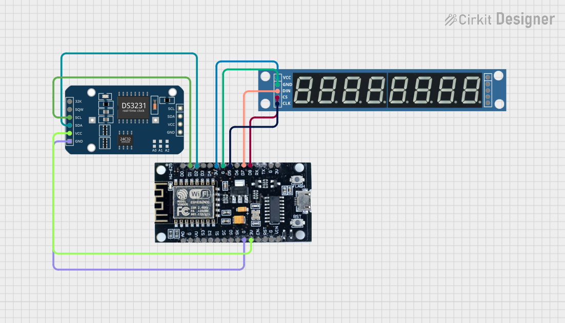
This document provides a detailed overview of a circuit that includes an ESP8266 microcontroller, a DS3231 RTC module, and a MAX7219 8-digit 7-segment display. The ESP8266 serves as the main controller, interfacing with the RTC module for timekeeping and the 7-segment display for visual output.
Component List
DS3231 RTC
- Description: Real-Time Clock module
- Pins: 32K, SQW, SCL, SDA, VCC, GND
MAX7219 8 Digit 7 Segment
- Description: 8-digit 7-segment display driver
- Pins: VCC, GND, DIN, CS, CLK, DOUT, LOAD
ESP8266
- Description: Wi-Fi microcontroller
- Pins: 3V, G, D8, D7, D6, D5, D4, D3, D2, D1, D0, A0, S3, S2, S1, SC, S0, SK, EN, VIN, RST, VU
Wiring Details
DS3231 RTC
- SCL connected to D1 of ESP8266
- SDA connected to D2 of ESP8266
- VCC connected to 3V of ESP8266
- GND connected to G of ESP8266
MAX7219 8 Digit 7 Segment
- VCC connected to 3V of ESP8266
- GND connected to G of ESP8266
- DIN connected to D7 of ESP8266
- CS connected to D8 of ESP8266
- CLK connected to D5 of ESP8266
ESP8266
- 3V connected to VCC of DS3231 RTC and MAX7219 8 Digit 7 Segment
- G connected to GND of DS3231 RTC and MAX7219 8 Digit 7 Segment
- D1 connected to SCL of DS3231 RTC
- D2 connected to SDA of DS3231 RTC
- D5 connected to CLK of MAX7219 8 Digit 7 Segment
- D7 connected to DIN of MAX7219 8 Digit 7 Segment
- D8 connected to CS of MAX7219 8 Digit 7 Segment
Code
No code is provided for this circuit.
This document provides a comprehensive overview of the circuit, including a summary, component list, wiring details, and code documentation. The components are clearly described, and the wiring details ensure proper connections between the components.