
Arduino Nano-Based SMS Alert System with IR Sensor and SIM800L
View and Edit Project In Cirkit Designer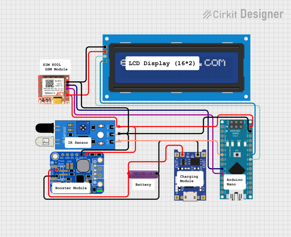
Circuit Documentation
Summary of the Circuit
This circuit integrates an Arduino Nano microcontroller with a SIM800L GSM module, an IR sensor, a 16x2 LCD screen with I2C interface, a TP4056 lithium battery charger module, a PowerBoost 1000 Basic module, and a 3.7V battery. The Arduino Nano serves as the central processing unit, interfacing with the IR sensor for input, the SIM800L module for cellular communication, and the LCD screen for displaying information. The PowerBoost 1000 Basic module is used to step up the voltage from the 3.7V battery to 5V required by the circuit, while the TP4056 module is responsible for charging the battery.
Component List
Arduino Nano
- Microcontroller board based on the ATmega328P
- Pins: D1/TX, D0/RX, RESET, GND, D2 to D13, VIN, 5V, A0 to A7, AREF, 3V3
SIM800L GSM Module
- GSM/GPRS module for cellular communication
- Pins: NFT, RING, VCC, DTR, RST, MIC+, RXD, MIC-, TXD, SPK+, GND, SPK-
IR Sensor
- Infrared sensor for detecting objects and motion
- Pins: out, gnd, vcc
3.7V Battery
- Lithium-ion battery for power supply
- Pins: +, -
TP4056
- Lithium battery charger module
- Pins: OUT-, B-, B+, OUT+, IN-, IN+
PowerBoost 1000 Basic
- Voltage step-up module to convert battery voltage to 5V
- Pins: VBAT, GND, ENABLE, LBO, 5.0V
LCD Screen 16x2 I2C
- Alphanumeric liquid crystal display with I2C interface
- Pins: SCL, SDA, VCC, GND
Wiring Details
Arduino Nano
- D4 connected to IR sensor output
- D7 connected to SIM800L TXD
- D8 connected to SIM800L RXD
- VIN connected to PowerBoost 5.0V
- GND connected to common ground
- A4 (SDA) connected to LCD screen SDA
- A5 (SCL) connected to LCD screen SCL
SIM800L GSM Module
- TXD connected to Arduino Nano D7
- RXD connected to Arduino Nano D8
- VCC connected to common VCC
- GND connected to common ground
IR Sensor
- out connected to Arduino Nano D4
- vcc connected to common VCC
- gnd connected to common ground
3.7V Battery
-
- connected to PowerBoost VBAT and TP4056 B+
-
- connected to PowerBoost GND and TP4056 B-
TP4056
- B+ connected to 3.7V battery +
- B- connected to 3.7V battery -
- OUT+ and OUT- not connected in this circuit
PowerBoost 1000 Basic
- VBAT connected to 3.7V battery +
- GND connected to 3.7V battery -
- 5.0V connected to common VCC
LCD Screen 16x2 I2C
- SCL connected to Arduino Nano A5
- SDA connected to Arduino Nano A4
- VCC connected to common VCC
- GND connected to common ground
Documented Code
Arduino Nano Code (sketch.ino)
void setup() {
  // put your setup code here, to run once:

}

void loop() {
  // put your main code here, to run repeatedly:

}
Note: The provided code is a template and does not include specific functionality. It should be populated with the required setup and loop code to control the circuit components as per the design requirements.