ESP32-Based Environmental Monitoring System with Motor Control
Circuit Documentation
Summary
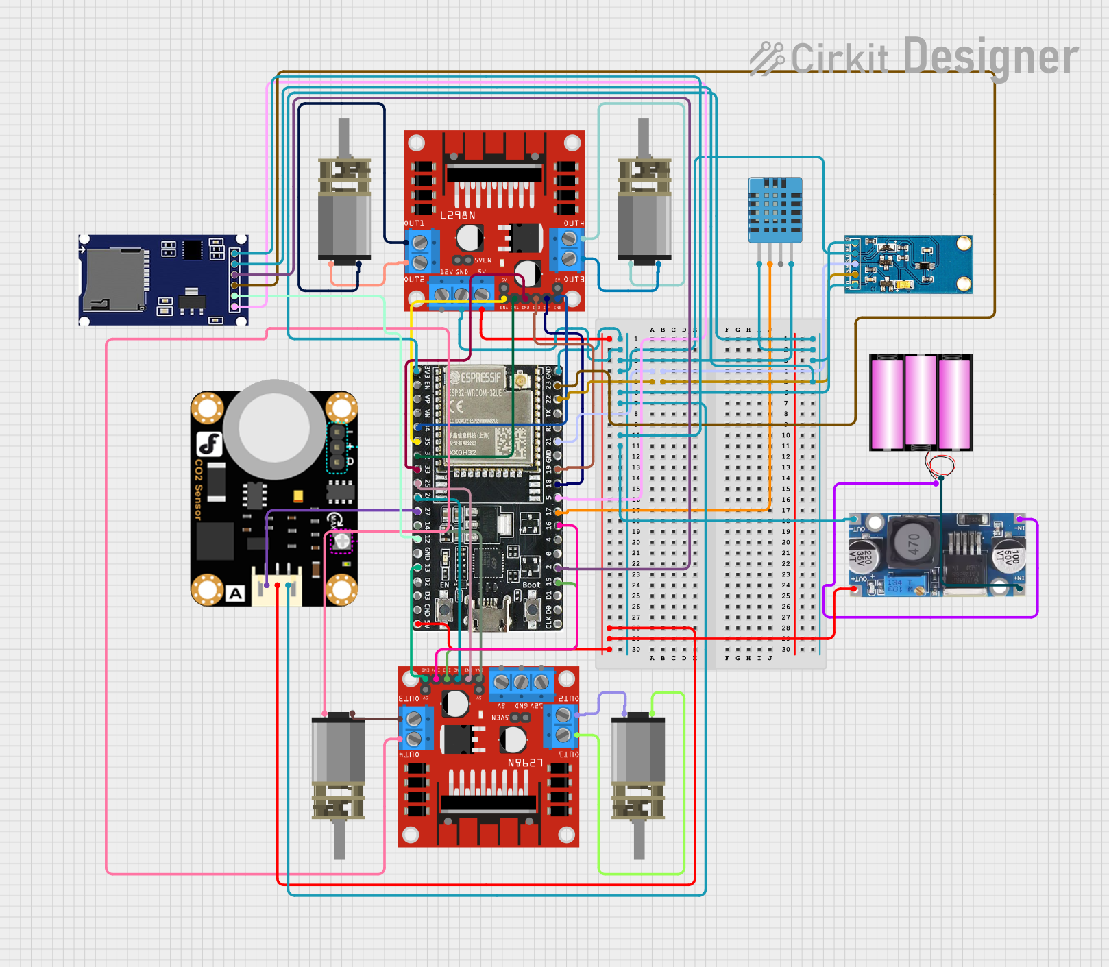
This circuit integrates various components to perform multiple functions. It includes an ESP32-WROOM-32UE microcontroller as the central processing unit, interfacing with sensors, motor drivers, and actuators. The circuit is designed to control DC motors, read environmental data from sensors, and communicate with peripheral devices through I2C and SPI protocols. A 12V battery powers the system, with a step-down buck converter providing regulated voltages for the microcontroller and sensors.
Component List
ESP32-WROOM-32UE
- Description: A powerful microcontroller with Wi-Fi and Bluetooth capabilities.
- Pins: 3v3, EN, VP, VN, 34, 35, 32, 33, 25, 26, 27, 14, 12, GND, 13, D2, D3, 5V, 23, 22, TX, RX, 21, 19, 18, 5, 17, 16, 4, 0, 2, 15, D1, D0, CKL
L298N DC Motor Driver (x2)
- Description: A dual H-bridge motor driver capable of driving two DC motors.
- Pins: OUT1, OUT2, 12V, GND, 5V, OUT3, OUT4, 5V-ENA-JMP-I, 5V-ENA-JMP-O, +5V-J1, +5V-J2, ENA, IN1, IN2, IN3, IN4, ENB
DC Mini Metal Gear Motor (x4)
- Description: A small DC motor with a gearbox for increased torque.
- Pins: IN1, IN2
DHT11 Humidity and Temperature Sensor
- Description: A basic, low-cost digital temperature and humidity sensor.
- Pins: VDD, DATA, NULL, GND
Light Sensor
- Description: A sensor module for detecting ambient light intensity.
- Pins: VCC, SCL, SDA, ADD, GND
SD Module
- Description: A module for reading and writing to SD cards using SPI.
- Pins: CS, SCK, MOSI, MISO, VCC, GND
Carbon Dioxide Sensor
- Description: A sensor for measuring the concentration of CO2 in the air.
- Pins: A, VCC, GND
Battery 12V
- Description: A 12V battery providing power to the circuit.
- Pins: +, -
Step Down Buck Converter
- Description: A DC-DC converter to step down the voltage from 12V to a lower level.
- Pins: IN +, IN - GND, OUT +, OUT - GND
Wiring Details
ESP32-WROOM-32UE
- 3v3: Connected to sensors' VCC pins.
- GND: Common ground with all components.
- 5V: Connected to the 5V pin of the L298N motor driver and the step-down buck converter's OUT +.
- GPIOs (21, 22, 32, 33, 34, 35, 25, 26, 27, 14, 19, 18, 5, 17, 16, 2, 15): Connected to various components for control and data acquisition.
L298N DC Motor Driver
- 5V: Receives power from the step-down buck converter.
- GND: Common ground with all components.
- ENA, ENB: Enable pins controlled by the ESP32.
- IN1, IN2, IN3, IN4: Input pins controlled by the ESP32 for motor direction.
- OUT1, OUT2, OUT3, OUT4: Connected to the DC Mini Metal Gear Motors.
DC Mini Metal Gear Motor
- IN1, IN2: Connected to the corresponding OUT pins of the L298N motor drivers.
DHT11 Humidity and Temperature Sensor
- VDD: Powered by the ESP32's 3v3 pin.
- DATA: Connected to a GPIO on the ESP32 for data reading.
- GND: Common ground with all components.
Light Sensor
- VCC: Powered by the ESP32's 3v3 pin.
- SCL, SDA: Connected to the ESP32's I2C pins for communication.
- GND: Common ground with all components.
SD Module
- VCC: Powered by the ESP32's 3v3 pin.
- CS, SCK, MOSI, MISO: Connected to the ESP32's SPI pins for communication.
- GND: Common ground with all components.
Carbon Dioxide Sensor
- VCC: Powered by the 5V output from the step-down buck converter.
- A: Analog output connected to a GPIO on the ESP32.
- GND: Common ground with all components.
Battery 12V
- +, -: Provides power to the step-down buck converter.
Step Down Buck Converter
- IN +, IN - GND: Connected to the 12V battery.
- OUT +, OUT - GND: Provides 5V output to the L298N motor driver and the Carbon Dioxide Sensor.
Documented Code
There is no code provided for the microcontroller. The documentation of the code would typically include descriptions of the functions, initialization routines, main loop, and any interrupt service routines. It would also detail how the microcontroller interfaces with each sensor and actuator, including the communication protocols used (e.g., I2C, SPI) and the logic for motor control.