Cirkit Designer
Your all-in-one circuit design IDE
Home /
Project Documentation
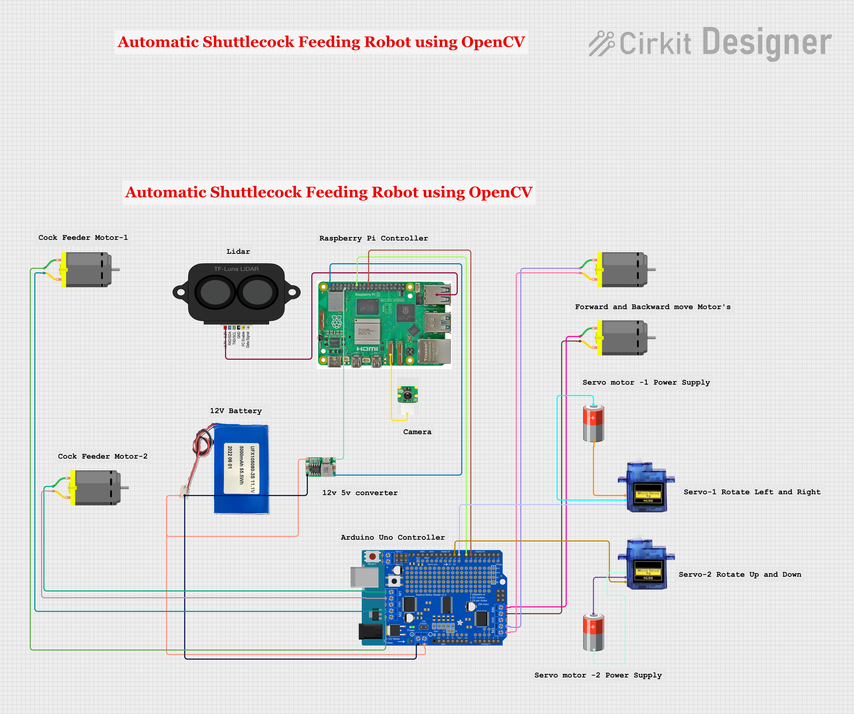
Raspberry Pi and Arduino-Based Battery-Powered Robotic System with Camera and LIDAR
Circuit Documentation
Summary
This document provides a detailed overview of a circuit that integrates various components including a Raspberry Pi 5, a Raspberry Pi Camera Module 2, a TF LUNA LIDAR, multiple DC motors, a Mini 360 Buck Converter, an Adafruit Motor, Stepper & Servo Shield, and several other components. The circuit is designed to interface these components for a variety of functionalities, including motor control, power management, and sensor integration.
Component List
Raspberry Pi Camera Module 2
- Description: Camera module for Raspberry Pi
- Pins: Camera Cable
TF LUNA LIDAR
- Description: LIDAR sensor for distance measurement
- Pins: power, RXD/SDA, TXD/SCL, GND, ICL, DATA SIG
Mini 360 Buck Converter
- Description: DC-DC buck converter for voltage regulation
- Pins: IN-, OUT-, OUT+, IN+
DC Motor
- Description: Standard DC motor
- Pins: pin 1, pin 2
Arduino UNO
- Description: Microcontroller board
- Pins: UNUSED, IOREF, Reset, 3.3V, 5V, GND, Vin, A0, A1, A2, A3, A4, A5, SCL, SDA, AREF, D13, D12, D11, D10, D9, D8, D7, D6, D5, D4, D3, D2, D1, D0
Raspberry Pi 5
- Description: Single-board computer
- Pins: Type-C, Micro HDMI 1, Micro HDMI 2, Camera 1, Camera 2, PoE, Fan, PCIe, USB 3.0, USB 2.0, Ethernet, 5V, GND, 3.3v, GPIO 14, GPIO 15, GPIO 18, GPIO 23, GPIO 24, GPIO 25, GPIO 8, GPIO 7, GPIO 1, GPIO 12, GPIO 16, GPIO 20, GPIO 21, GPIO 2, GPIO 3, GPIO 4, GPIO 17, GPIO 27, GPIO 22, GPIO 10, GPIO 9, GPIO 11, GPIO 0, GPIO 5, GPIO 6, GPIO 13, GPIO 19, GPIO 26
Li-ion 5000mah
- Description: Lithium-ion battery
- Pins: 11.1V, GND
Adafruit Motor, Stepper & Servo Shield
- Description: Shield for motor, stepper, and servo control
- Pins: AD3, AD2, AD1, AD0, D0, D1, D2, D3, D4, D5, D6, D7, PWM0, PWM1, PWM14, PWM15, VIN, GND, +5V, +3V3, /RST, IOREF, AD5/SCL, AD4/SDA, AREF, D13, D12, D11, D10, D9, D8, MISO, MOSI, SCK, M1A, M1B, M2B, M2A, M3A, M3B, M4B, M4A, VMOTOR
Micro servo 9G
- Description: Small servo motor
- Pins: GND, +5V, PWM
5v Battery
- Description: 5V battery
- Pins: +, -
Wiring Details
Raspberry Pi Camera Module 2
- Camera Cable connected to Camera 1 on Raspberry Pi 5
TF LUNA LIDAR
- power connected to USB 2.0 on Raspberry Pi 5
Mini 360 Buck Converter
- OUT+ connected to 5V on Raspberry Pi 5
- OUT- connected to GND on Raspberry Pi 5
- IN+ connected to 11.1V on Li-ion 5000mah
- IN- connected to GND on Li-ion 5000mah
DC Motor (1)
- pin 1 connected to M4A on Adafruit Motor, Stepper & Servo Shield
- pin 2 connected to M4B on Adafruit Motor, Stepper & Servo Shield
DC Motor (2)
- pin 1 connected to M3B on Adafruit Motor, Stepper & Servo Shield
- pin 2 connected to M3A on Adafruit Motor, Stepper & Servo Shield
DC Motor (3)
- pin 1 connected to M2A on Adafruit Motor, Stepper & Servo Shield
- pin 2 connected to M2B on Adafruit Motor, Stepper & Servo Shield
DC Motor (4)
- pin 1 connected to M1A on Adafruit Motor, Stepper & Servo Shield
- pin 2 connected to M1B on Adafruit Motor, Stepper & Servo Shield
Adafruit Motor, Stepper & Servo Shield
- D7 connected to GPIO 23 on Raspberry Pi 5
- D6 connected to GPIO 25 on Raspberry Pi 5
- VMOTOR connected to 11.1V on Li-ion 5000mah
- GND connected to GND on Li-ion 5000mah
Micro servo 9G (1)
- PWM connected to D8 on Adafruit Motor, Stepper & Servo Shield
- GND connected to - on 5v Battery
- +5V connected to + on 5v Battery
Micro servo 9G (2)
- PWM connected to D9 on Adafruit Motor, Stepper & Servo Shield
- GND connected to - on 5v Battery
- +5V connected to + on 5v Battery
Documented Code
Arduino UNO Code
void setup() {
  // put your setup code here, to run once:

}

void loop() {
  // put your main code here, to run repeatedly:

}
Documentation File
- File Name: documentation.txt
- Content: (Empty)
This concludes the detailed documentation of the circuit, including the summary, component list, wiring details, and code.