
Arduino Nano Line Follower Robot with PID Control and L298N Motor Driver
View and Edit Project In Cirkit Designer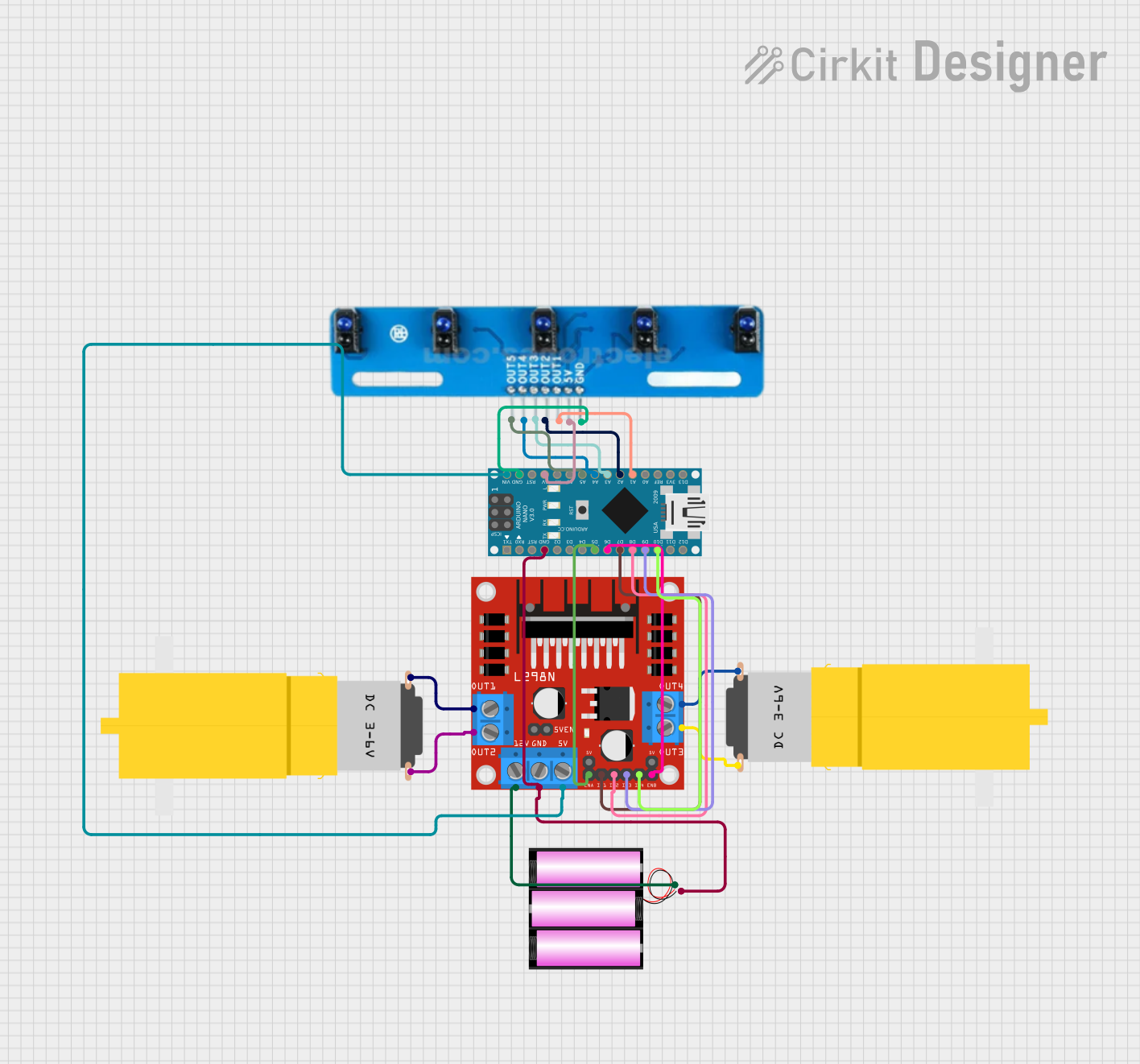
Circuit Documentation
Summary
This document provides a detailed overview of a line follower robot circuit. The circuit uses an Arduino Nano microcontroller to read values from a 5-channel IR sensor array and control two DC motors via an L298N motor driver. The motors are driven using PWM signals, and the robot follows a line using a PID control algorithm.
Component List
Arduino Nano
- Description: A small, complete, and breadboard-friendly board based on the ATmega328P.
- Pins: D1/TX, D0/RX, RESET, GND, D2, D3, D4, D5, D6, D7, D8, D9, D10, D11/MOSI, D12/MISO, VIN, 5V, A7, A6, A5, A4, A3, A2, A1, A0, AREF, 3V3, D13/SCK
5-channel IR array
- Description: An array of 5 infrared sensors used to detect the line.
- Pins: A5, A4, A3, A2, A1, VCC, GND
L298N DC motor driver
- Description: A dual H-bridge motor driver that allows control of the speed and direction of two DC motors.
- Pins: OUT1, OUT2, 12V, GND, 5V, OUT3, OUT4, 5V-ENA-JMP-I, 5V-ENA-JMP-O, +5V-J1, +5V-J2, ENA, IN1, IN2, IN3, IN4, ENB
Motor amarillo motorreductor hobby (2 units)
- Description: A small DC motor with a gearbox, commonly used in hobby projects.
- Pins: vcc, GND
Battery 12V
- Description: A 12V battery used to power the circuit.
- Pins: +, -
Wiring Details
Arduino Nano
GND connected to:
- L298N DC motor driver GND
- Battery 12V -
- 5-channel IR array GND
D5 connected to L298N DC motor driver ENA
D6 connected to L298N DC motor driver ENB
D7 connected to L298N DC motor driver IN1
D8 connected to L298N DC motor driver IN2
D9 connected to L298N DC motor driver IN3
D10 connected to L298N DC motor driver IN4
VIN connected to L298N DC motor driver 5V
5V connected to 5-channel IR array VCC
A5 connected to 5-channel IR array A5
A4 connected to 5-channel IR array A4
A3 connected to 5-channel IR array A3
A2 connected to 5-channel IR array A2
A1 connected to 5-channel IR array A1
5-channel IR array
GND connected to Arduino Nano GND
VCC connected to Arduino Nano 5V
A5 connected to Arduino Nano A5
A4 connected to Arduino Nano A4
A3 connected to Arduino Nano A3
A2 connected to Arduino Nano A2
A1 connected to Arduino Nano A1
L298N DC motor driver
GND connected to:
- Arduino Nano GND
- Battery 12V -
ENA connected to Arduino Nano D5
ENB connected to Arduino Nano D6
IN1 connected to Arduino Nano D7
IN2 connected to Arduino Nano D8
IN3 connected to Arduino Nano D9
IN4 connected to Arduino Nano D10
5V connected to Arduino Nano VIN
OUT1 connected to Motor amarillo motorreductor hobby GND
OUT2 connected to Motor amarillo motorreductor hobby vcc
12V connected to Battery 12V +
OUT3 connected to Motor amarillo motorreductor hobby GND
OUT4 connected to Motor amarillo motorreductor hobby vcc
Motor amarillo motorreductor hobby (2 units)
GND connected to:
- L298N DC motor driver OUT1 (for the first motor)
- L298N DC motor driver OUT3 (for the second motor)
vcc connected to:
- L298N DC motor driver OUT2 (for the first motor)
- L298N DC motor driver OUT4 (for the second motor)
Battery 12V
- connected to:
- L298N DC motor driver GND
- Arduino Nano GND
+ connected to L298N DC motor driver 12V
Documented Code
/*
 * Arduino Nano Line Follower Robot with PID Control
 *
 * This code reads values from a 5-channel IR sensor array to follow a line.
 * It uses a PID controller to adjust the speed of two DC motors via an L298N
 * motor driver. The motors are controlled using PWM signals.
 */

// Pin definitions
const int irPins[5] = {A1, A2, A3, A4, A5};
const int motorLeftPWM = 5;
const int motorRightPWM = 6;
const int motorLeftDir1 = 7;
const int motorLeftDir2 = 8;
const int motorRightDir1 = 9;
const int motorRightDir2 = 10;

// PID constants
float Kp = 1.0;
float Ki = 0.0;
float Kd = 0.0;

// PID variables
float error = 0;
float previousError = 0;
float integral = 0;
float derivative = 0;
float correction = 0;

// Motor speed
int baseSpeed = 150;
int maxSpeed = 255;

void setup() {
  // Initialize motor control pins
  pinMode(motorLeftPWM, OUTPUT);
  pinMode(motorRightPWM, OUTPUT);
  pinMode(motorLeftDir1, OUTPUT);
  pinMode(motorLeftDir2, OUTPUT);
  pinMode(motorRightDir1, OUTPUT);
  pinMode(motorRightDir2, OUTPUT);

  // Initialize IR sensor pins
  for (int i = 0; i < 5; i++) {
    pinMode(irPins[i], INPUT);
  }
}

void loop() {
  // Read IR sensor values
  int irValues[5];
  for (int i = 0; i < 5; i++) {
    irValues[i] = analogRead(irPins[i]);
  }

  // Calculate error
  error = (irValues[0] * -2 + irValues[1] * -1 + irValues[2] * 0 +
           irValues[3] * 1 + irValues[4] * 2);

  // PID calculations
  integral += error;
  derivative = error - previousError;
  correction = Kp * error + Ki * integral + Kd * derivative;
  previousError = error;

  // Calculate motor speeds
  int leftSpeed = baseSpeed - correction;
  int rightSpeed = baseSpeed + correction;

  // Constrain motor speeds
  leftSpeed = constrain(leftSpeed, 0, maxSpeed);
  rightSpeed = constrain(rightSpeed, 0, maxSpeed);

  // Set motor directions and speeds
  if (leftSpeed >= 0) {
    digitalWrite(motorLeftDir1, HIGH);
    digitalWrite(motorLeftDir2, LOW);
  } else {
    digitalWrite(motorLeftDir1, LOW);
    digitalWrite(motorLeftDir2, HIGH);
    leftSpeed = -leftSpeed;
  }
  if (rightSpeed >= 0) {
    digitalWrite(motorRightDir1, HIGH);
    digitalWrite(motorRightDir2, LOW);
  } else {
    digitalWrite(motorRightDir1, LOW);
    digitalWrite(motorRightDir2, HIGH);
    rightSpeed = -rightSpeed;
  }

  // Apply PWM to motors
  analogWrite(motorLeftPWM, leftSpeed);
  analogWrite(motorRightPWM, rightSpeed);

  // Small delay
  delay(10);
}
This code initializes the motor control and IR sensor pins, reads the IR sensor values, calculates the error for the PID controller, and adjusts the motor speeds accordingly to follow a line. The PID controller helps in maintaining a smooth and accurate line-following behavior.