
Arduino UNO-Based Automated Plant Watering System with Soil Moisture Sensor and LCD Display
View and Edit Project In Cirkit Designer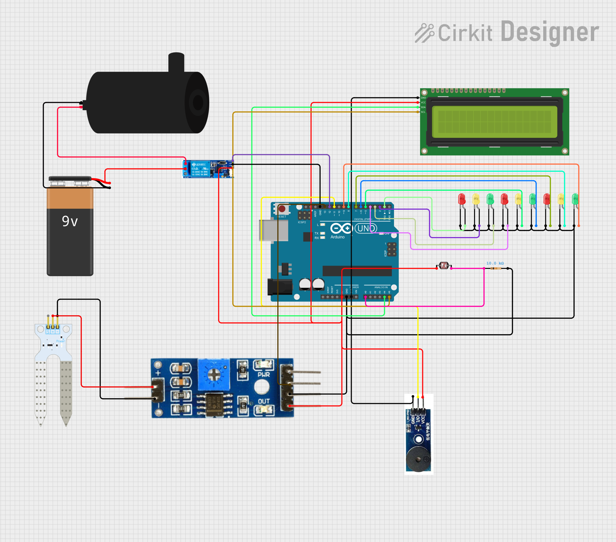
Circuit Documentation
Summary
This circuit is designed to monitor soil moisture levels and control a water pump based on the moisture readings. It also includes an LCD display for visual feedback, an active buzzer for alerts, and multiple LEDs for status indication. The circuit is controlled by an Arduino UNO microcontroller.
Component List
Arduino UNO
- Description: Microcontroller board based on the ATmega328P.
- Pins: UNUSED, IOREF, Reset, 3.3V, 5V, GND, Vin, A0, A1, A2, A3, A4, A5, SCL, SDA, AREF, D13, D12, D11, D10, D9, D8, D7, D6, D5, D4, D3, D2, D1, D0
Soil Moisture Module
- Description: Module to measure soil moisture levels.
- Pins: positive, negative, Analog, Digital, Ground, VCC
16x2 I2C LCD
- Description: LCD display with I2C interface.
- Pins: GND, VCC, SDA, SCL
Relay module 5v-30v
- Description: Relay module to control high voltage devices.
- Pins: common contact, normally open, normally closed, trigger, V-, V+
Active Buzzer Module
- Description: Buzzer for audio alerts.
- Pins: GND, I/O, VCC
Water Pump
- Description: Pump to water plants.
- Pins: positive, negative
Soil Moisture Sensor
- Description: Sensor to detect soil moisture.
- Pins: VCC, GND, SIG
9V Battery
- Description: Power source.
- Pins: -, +
Photocell (LDR)
- Description: Light-dependent resistor.
- Pins: pin 0, pin 1
LED: Two Pin (red)
- Description: Red LED for status indication.
- Pins: cathode, anode
Resistor
- Description: Resistor with 10k Ohms resistance.
- Pins: pin1, pin2
LED: Two Pin (green)
- Description: Green LED for status indication.
- Pins: cathode, anode
LED: Two Pin (yellow)
- Description: Yellow LED for status indication.
- Pins: cathode, anode
Wiring Details
Arduino UNO
- 5V: Connected to VCC of Active Buzzer Module, Relay module 5v-30v, 16x2 I2C LCD, Soil Moisture Module, and pin 0 of Photocell (LDR).
- GND: Connected to GND of Active Buzzer Module, 16x2 I2C LCD, Relay module 5v-30v, Soil Moisture Module, and cathodes of all LEDs.
- A0: Connected to pin1 of Resistor and pin 1 of Photocell (LDR).
- A4: Connected to SDA of 16x2 I2C LCD.
- A5: Connected to SCL of 16x2 I2C LCD.
- D13: Connected to Digital pin of Soil Moisture Module.
- D12: Connected to trigger pin of Relay module 5v-30v.
- D11: Connected to I/O pin of Active Buzzer Module.
- D9: Connected to anode of green LED.
- D8: Connected to anode of yellow LED.
- D7: Connected to anode of red LED.
- D6: Connected to anode of green LED.
- D5: Connected to anode of yellow LED.
- D4: Connected to anode of red LED.
- D3: Connected to anode of green LED.
- D2: Connected to anode of yellow LED.
- D1: Connected to anode of red LED.
Soil Moisture Module
- VCC: Connected to VCC of Soil Moisture Sensor.
- Ground: Connected to GND of Soil Moisture Sensor.
- Digital: Connected to D13 of Arduino UNO.
16x2 I2C LCD
- VCC: Connected to 5V of Arduino UNO.
- GND: Connected to GND of Arduino UNO.
- SDA: Connected to A4 of Arduino UNO.
- SCL: Connected to A5 of Arduino UNO.
Relay module 5v-30v
- V+: Connected to 5V of Arduino UNO.
- V-: Connected to GND of Arduino UNO.
- trigger: Connected to D12 of Arduino UNO.
- common contact: Connected to + of 9V Battery.
- normally open: Connected to positive pin of Water Pump.
Active Buzzer Module
- VCC: Connected to 5V of Arduino UNO.
- GND: Connected to GND of Arduino UNO.
- I/O: Connected to D11 of Arduino UNO.
Water Pump
- positive: Connected to normally open pin of Relay module 5v-30v.
- negative: Connected to - of 9V Battery.
Photocell (LDR)
- pin 0: Connected to 5V of Arduino UNO.
- pin 1: Connected to pin1 of Resistor and A0 of Arduino UNO.
LEDs
- Red LED (1):
- cathode: Connected to GND of Arduino UNO.
- anode: Connected to D4 of Arduino UNO.
- Red LED (2):
- cathode: Connected to GND of Arduino UNO.
- anode: Connected to D7 of Arduino UNO.
- Red LED (3):
- cathode: Connected to GND of Arduino UNO.
- anode: Connected to D1 of Arduino UNO.
- Green LED (1):
- cathode: Connected to GND of Arduino UNO.
- anode: Connected to D9 of Arduino UNO.
- Green LED (2):
- cathode: Connected to GND of Arduino UNO.
- anode: Connected to D6 of Arduino UNO.
- Green LED (3):
- cathode: Connected to GND of Arduino UNO.
- anode: Connected to D3 of Arduino UNO.
- Yellow LED (1):
- cathode: Connected to GND of Arduino UNO.
- anode: Connected to D8 of Arduino UNO.
- Yellow LED (2):
- cathode: Connected to GND of Arduino UNO.
- anode: Connected to D5 of Arduino UNO.
- Yellow LED (3):
- cathode: Connected to GND of Arduino UNO.
- anode: Connected to D2 of Arduino UNO.
Resistor
- pin1: Connected to A0 of Arduino UNO and pin 1 of Photocell (LDR).
- pin2: Connected to GND of Arduino UNO.
Code Documentation
Arduino UNO Code
void setup() {
  Serial.begin(9600);
  Serial.println("Setup complete");
}

void loop() {
  Serial.println("Loop running");
  delay(1000);
}
This code initializes the serial communication at a baud rate of 9600 in the setup() function and prints "Setup complete" to the serial monitor. In the loop() function, it continuously prints "Loop running" every second.