
Arduino UNO Smart Light Control with BH1750 Light Sensor and Relay Module
View and Edit Project In Cirkit Designer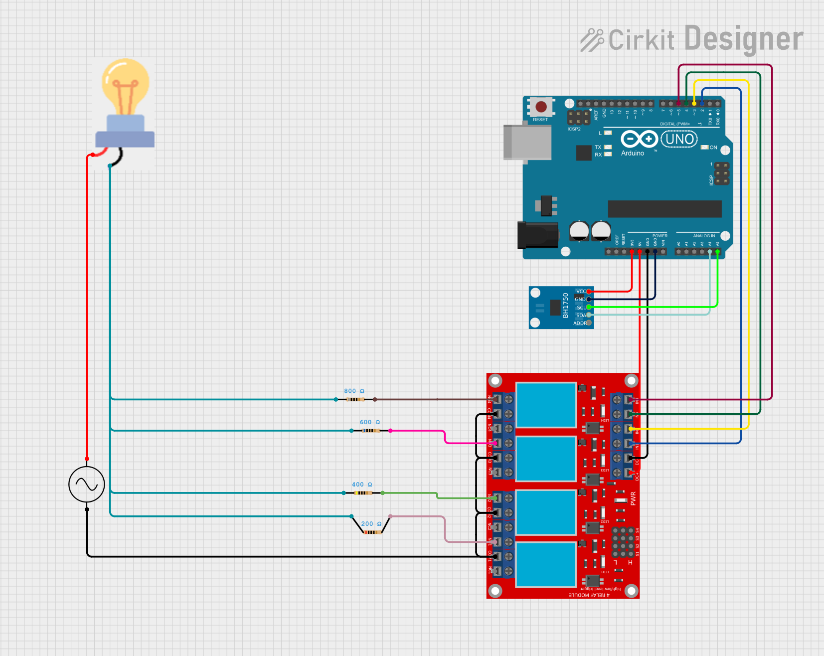
Circuit Documentation
Summary
This circuit involves an Arduino UNO microcontroller interfacing with a BH1750 light sensor and a 4-channel relay module. The relays control the power to a bulb through a series of resistors. The circuit is powered by an AC supply.
Component List
Arduino UNO
- Description: A microcontroller board based on the ATmega328P.
- Pins: UNUSED, IOREF, Reset, 3.3V, 5V, GND, Vin, A0, A1, A2, A3, A4, A5, SCL, SDA, AREF, D13, D12, D11, D10, D9, D8, D7, D6, D5, D4, D3, D2, D1, D0
BH1750
- Description: A digital light sensor.
- Pins: VCC, GND, SCL, SDA, ADDR
4 Channel Relay Module
- Description: A module with 4 relays for controlling high voltage devices.
- Pins: N.O. 4, COM 4, N.C. 4, N.O. 3, COM 3, N.C. 3, N.O. 2, COM 2, N.C. 2, N.O. 1, COM 1, N.C. 1, Pin 13, Pin 14, Pin 15, Pin 16, Pin 17, Pin 18, Pin 19, Pin 20, Pin 21, Pin 22, Pin 23, Pin 24, VCC+, VCC- (GND), IN 1, IN 2, IN 3, IN 4
Bulb
- Description: A standard light bulb.
- Pins: GND, power
AC Supply
- Description: An AC power supply.
- Pins: +ve, -ve
Resistors
- Description: Resistors with various resistance values.
- Pins: pin1, pin2
- Properties:
- Resistor 1: 200 Ohms
- Resistor 2: 400 Ohms
- Resistor 3: 600 Ohms
- Resistor 4: 800 Ohms
Wiring Details
Arduino UNO
- 3.3V connected to BH1750 VCC
- 5V connected to 4 Channel Relay Module VCC+
- GND connected to 4 Channel Relay Module VCC- (GND)
- GND connected to BH1750 GND
- A4 connected to BH1750 SDA
- A5 connected to BH1750 SCL
- D5 connected to 4 Channel Relay Module IN 4
- D4 connected to 4 Channel Relay Module IN 3
- D3 connected to 4 Channel Relay Module IN 2
- D2 connected to 4 Channel Relay Module IN 1
BH1750
- VCC connected to Arduino UNO 3.3V
- GND connected to Arduino UNO GND
- SDA connected to Arduino UNO A4
- SCL connected to Arduino UNO A5
4 Channel Relay Module
- VCC+ connected to Arduino UNO 5V
- VCC- (GND) connected to Arduino UNO GND
- IN 4 connected to Arduino UNO D5
- IN 3 connected to Arduino UNO D4
- IN 2 connected to Arduino UNO D3
- IN 1 connected to Arduino UNO D2
- N.O. 4 connected to Resistor 4 pin2
- N.O. 3 connected to Resistor 3 pin2
- N.O. 2 connected to Resistor 2 pin2
- N.O. 1 connected to Resistor 1 pin2
- COM 4, COM 3, COM 2, COM 1 connected to AC Supply -ve
Bulb
- GND connected to Resistor 1 pin1, Resistor 2 pin1, Resistor 3 pin1, Resistor 4 pin1
- power connected to AC Supply +ve
AC Supply
- +ve connected to Bulb power
- -ve connected to 4 Channel Relay Module COM 4, COM 3, COM 2, COM 1
Resistors
- Resistor 1: pin1 connected to Bulb GND, pin2 connected to 4 Channel Relay Module N.O. 1
- Resistor 2: pin1 connected to Bulb GND, pin2 connected to 4 Channel Relay Module N.O. 2
- Resistor 3: pin1 connected to Bulb GND, pin2 connected to 4 Channel Relay Module N.O. 3
- Resistor 4: pin1 connected to Bulb GND, pin2 connected to 4 Channel Relay Module N.O. 4
Documented Code
Arduino UNO Code (sketch.ino)
void setup() {
  // put your setup code here, to run once:

}

void loop() {
  // put your main code here, to run repeatedly:

}
Additional Documentation (documentation.txt)