
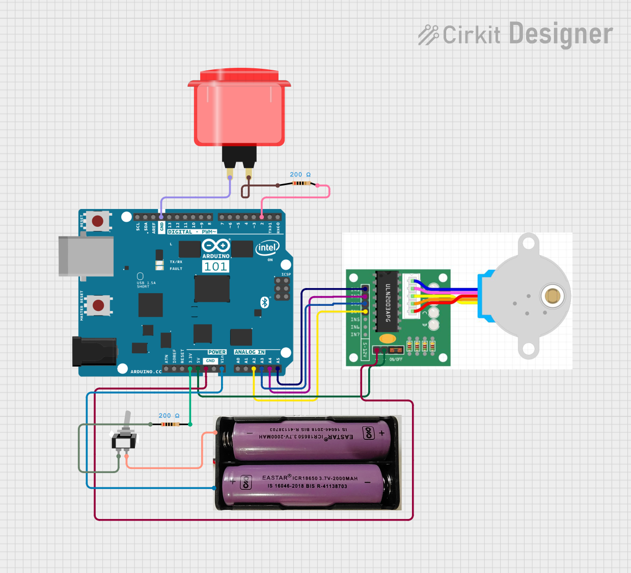
Circuit Documentation
Summary
This circuit involves an Arduino 101 microcontroller, a stepper motor, a 7.4V power supply, a toggle switch, resistors, and an arcade button. The Arduino 101 controls the stepper motor based on the state of the arcade button. The circuit is powered by a 7.4V power supply, and the toggle switch is used to control the power to the circuit.
Component List
Arduino 101
- Description: Microcontroller board based on the Intel Curie module.
- Pins: A5/SCL, A4/SDA, AREF, GND, D13/SCK, D12/MISO, D11 PWM/MOSI, D10 PWM/SS, D9 PWM, D8, D7, D6 PWM, D5 PWM, D4, D3 PWM, D2, D1/TX, D0/RX, AIN, ioref, RESET, 3V3, 5V, VIN, A0, A1, A2, A3, ICSP MISO, ICSP SCK, ICSP MOSI
Stepper Motor
- Description: Stepper motor with four control pins and power pins.
- Pins: IN1, IN2, IN3, IN4, +, -
7.4V Power Supply
- Description: Power supply providing 7.4V.
- Pins: +, -
Toggle Switch (SPST)
- Description: Single-pole single-throw toggle switch.
- Pins: L1, COM
Resistor (200 Ohms)
- Description: Resistor with a resistance of 200 Ohms.
- Pins: pin1, pin2
Arcade Button (Red)
- Description: Arcade button with a single pin.
- Pins: no name yet
Wiring Details
Arduino 101
- A5/SCL connected to IN1 of the Stepper Motor.
- A4/SDA connected to IN2 of the Stepper Motor.
- A3 connected to IN3 of the Stepper Motor.
- A2 connected to IN4 of the Stepper Motor.
- D2 connected to pin2 of the Resistor.
- 3V3 connected to pin2 of the Resistor.
- 5V connected to + of the Stepper Motor.
- GND connected to no name yet of the Arcade Button.
- GND connected to - of the Stepper Motor.
- VIN connected to + of the 7.4V Power Supply.
Stepper Motor
- IN1 connected to A5/SCL of the Arduino 101.
- IN2 connected to A4/SDA of the Arduino 101.
- IN3 connected to A3 of the Arduino 101.
- IN4 connected to A2 of the Arduino 101.
- + connected to 5V of the Arduino 101.
- - connected to GND of the Arduino 101.
7.4V Power Supply
- + connected to VIN of the Arduino 101.
- - connected to COM of the Toggle Switch.
Toggle Switch (SPST)
- L1 connected to pin1 of the Resistor.
- COM connected to - of the 7.4V Power Supply.
Resistor (200 Ohms)
- pin1 connected to L1 of the Toggle Switch.
- pin2 connected to 3V3 of the Arduino 101.
- pin2 connected to D2 of the Arduino 101.
Arcade Button (Red)
- no name yet connected to GND of the Arduino 101.
- no name yet connected to pin1 of the Resistor.
Code Documentation
#include <Stepper.h>

// Define the number of steps per revolution for your motor
#define STEPS_PER_REV 200

// Initialize the stepper library on the pins connected to the motor
Stepper stepper(STEPS_PER_REV, A5, A4, A3, A2);

// Define the button pin
const int buttonPin = 2;

// Variable to store the button state
int buttonState = 0;

void setup() {
  // Set the speed of the motor in RPM
  stepper.setSpeed(60);

  // Initialize the button pin as an input
  pinMode(buttonPin, INPUT);
}

void loop() {
  // Read the state of the button
  buttonState = digitalRead(buttonPin);

  // Check if the button is pressed
  if (buttonState == HIGH) {
    // Define the number of steps for each interval
    int stepsPerInterval = 50; // Adjust this value as needed

    // Rotate the motor a specific number of steps in one direction
    stepper.step(stepsPerInterval);
    delay(1000); // Wait for a second

    // Rotate the motor a specific number of steps in the opposite direction
    stepper.step(-stepsPerInterval);
    delay(1000); // Wait for a second
  }
}
This code initializes the stepper motor and the arcade button. When the button is pressed, the stepper motor rotates a specific number of steps in one direction, waits for a second, and then rotates the same number of steps in the opposite direction. The speed of the motor is set to 60 RPM.